LIGHTING SYSTEM ALL Stop Light do not Illuminate
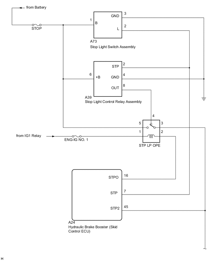
WIRING DIAGRAM
PROCEDURE
-
CHECK STOP LIGHT OPERATION
-
Check that the stop lights illuminate when the brake pedal is depressed.
OK The stop lights illuminate when the brake pedal is depressed.
OK 
CHECK CONNECTOR CONNECTION CONDITION
NG 
-
-
CHECK HARNESS AND CONNECTOR (OUT)
-
Disconnect the A24 hydraulic brake booster (skid control ECU) connector.
-
Disconnect the A39 stop light control relay connector.
-
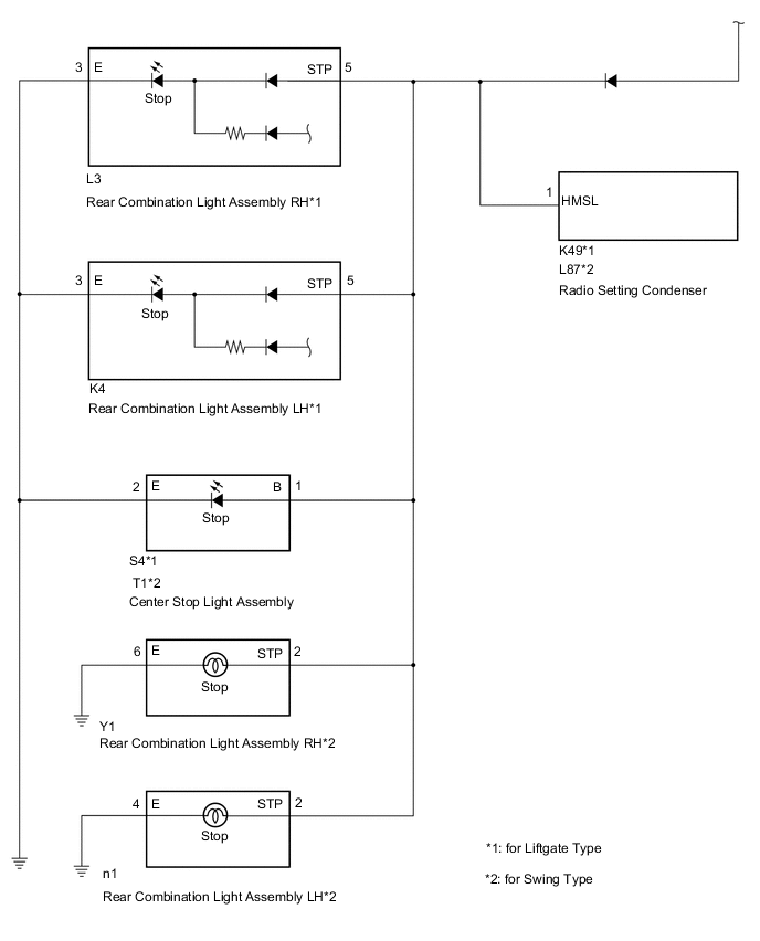
Disconnect the S4 or T1 center stop light assembly connector.
-
Disconnect the L3 or Y1 rear combination light assembly RH connector.
-
Disconnect the K4 or n1 rear combination light assembly LH connector.
-
Disconnect the K49 or L87 radio setting condenser connector.
-
Measure the resistance according to the value(s) in the table below.
Standard Resistance Tester Connection Condition Specified Condition A24-45 (STP2) - A39-8 (OUT) Always Below 1 Ω A24-45 (STP2) - Body ground Always 10 kΩ or higher
NG
REPAIR OR REPLACE HARNESS OR CONNECTOR
OK
-
-
CHECK STOP LIGHT CONTROL RELAY ASSEMBLY (OUT)
-
Disconnect the S4 or T1 center stop light assembly connector.
-
Disconnect the L3 or Y1 rear combination light assembly RH connector.
-
Disconnect the K4 or n1 rear combination light assembly LH connector.
-
Disconnect the K49 or L87 radio setting condenser connector.
-
Measure the voltage according to the value(s) in the table below.
Standard Voltage Tester Connection Condition Specified Condition A39-8 (OUT) - Body ground Brake pedal depressed 11 to 14 V
OK
REPAIR OR REPLACE REPAIR OR REPLACE CENTER STOP LIGHT ASSEMBLY, REAR COMBINATION LIGHT ASSEMBLY AND RADIO SETTING CONDENSER
NG
REPLACE STOP LIGHT CONTROL RELAY ASSEMBLY
-