LIGHTING SYSTEM Illumination Circuit
DESCRIPTION
When a door is opened while the DOOR switch of the map light assembly is on, the map light assembly receives a door open signal from the main body ECU and turns on the corresponding lights.
WIRING DIAGRAM
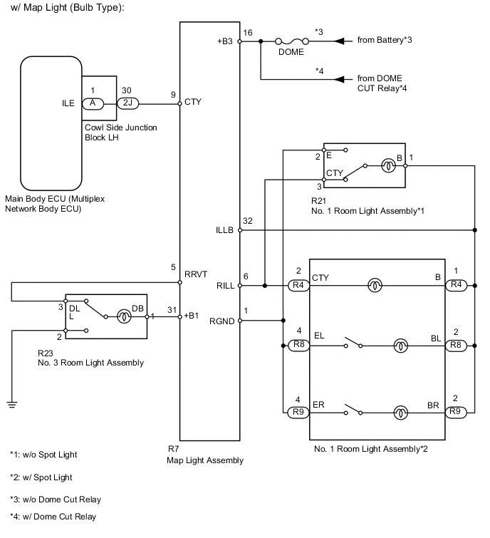
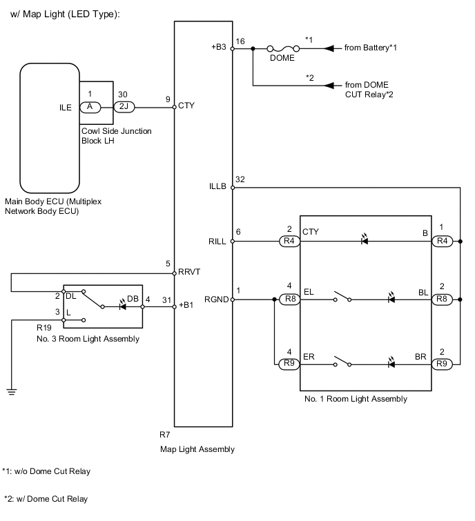
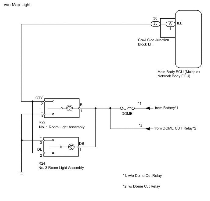
CAUTION / NOTICE / HINT
Note
Inspect the fuses for circuits related to this system before performing the following inspection procedure.
PROCEDURE
-
PERFORM ACTIVE TEST USING GTS
-
Operate the GTS according to the steps on the display and select "Active Test".
Main Body Tester Display Test Part Control Range Diagnostic Note Illuminated Entry System Illumination light OFF or ON - OK Light comes on.
OK 
PROCEED TO NEXT CIRCUIT INSPECTION SHOWN IN PROBLEM SYMPTOMS TABLE Click here
NG 
-
-
CHECK VEHICLE TYPE
-
Check the vehicle type.
Result Result Proceed to w/o Map Light A w/ Map Light B
B 
CHECK HARNESS AND CONNECTOR (MAP LIGHT - BODY GROUND) Click here
A
-
-
CHECK HARNESS AND CONNECTOR (MAIN BODY ECU - NO. 1 ROOM LIGHT AND NO. 3 ROOM LIGHT)
-
Disconnect the 2J main body ECU connector.
-
Disconnect the R22 No. 1 room light connector.
-
Measure the resistance according to the value(s) in the table below.
Standard Resistance Tester Connection Condition Specified Condition 2J-30 (ILE) - R22-2 (CTY) Always Below 1 Ω R22-1 (B) - Body ground R22-3 (E) - Body ground 2J-30 (ILE) - Body ground Always 10 kΩ or higher -
Disconnect the R24 No. 1 room light connector.
-
Measure the resistance according to the value(s) in the table below.
Standard Resistance Tester Connection Condition Specified Condition 2J-30 (ILE) - R24-2 (DL) Always Below 1 Ω R24-1 (DB) - Body ground R24-3 (L) - Body ground 2J-30 (ILE) - Body ground Always 10 kΩ or higher
OK
REPLACE MAIN BODY ECU (MULTIPLEX NETWORK BODY ECU)
NG
REPAIR OR REPLACE HARNESS AND CONNECTOR
-
-
CHECK HARNESS AND CONNECTOR (MAP LIGHT - BODY GROUND)
-
*1 Component with harness connected: (Map Light Assembly) Disconnect the 2J ECU connector.
-
Measure the voltage according to the value(s) in the table below.
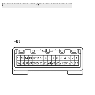
Standard Voltage Tester Connection Condition Specified Condition R7-16 (+B3) - Body ground Always 11 to 14 V
NG
REPAIR OR REPLACE HARNESS AND CONNECTOR
OK
-
-
INSPECT MAP LIGHT
-
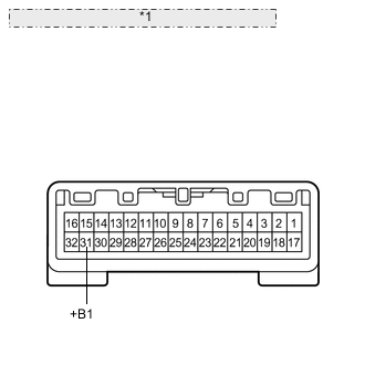
*1 Component with harness connected: (Map Light) Remove the map light Click here.
-
Measure the voltage according to the value(s) in the table below.
Standard Voltage Tester Connection Switch Condition Specified Condition R7-31 (+B1) - R7-5 (RRVT) Dome light switch off Below 1 V Dome light switch on 11 to 14 V R7-6 (RILL) - R7-32 (ILLB) Dome light switch off Below 1 V Dome light switch on 11 to 14 V -
Measure the resistance according to the value(s) in the table below.
Standard Resistance Tester Connection Switch Condition Specified Condition R7-9 (CTY) - Body ground "Door" switch on and door open Below 1 Ω "Door" switch off and door open 10 kΩ or higher "Door" switch on and door closed 10 kΩ or higher "Door" switch off and door closed 10 kΩ or higher R7-17 (GND9) - Body ground Always Below 1 Ω
NG
REPLACE MAP LIGHT Click here
OK
-
-
CHECK HARNESS AND CONNECTOR (NO. 3 ROOM LIGHT - MAP LIGHT AND BODY GROUND)
-
Disconnect the R7 map light connector.
-
Disconnect the R23 light connector.
-
Measure the resistance according to the value(s) in the table below.
Standard Resistance Tester Connection Condition Specified Condition R7-31 (+B1) - R23-1 (DB) Always Below 1 Ω R7-5 (RRVT) - R23-3 (DL) R23-2 (L) - Body ground R7-31 (+B1) - Body ground Always 10 kΩ or higher R7-16 (RRVT) - Body ground
NG
REPAIR OR REPLACE HARNESS AND CONNECTOR
OK
-
-
CHECK VEHICLE TYPE
-
Check the vehicle type.
Result Result Proceed to w/ Spot light A w/o Spot light B
B
CHECK HARNESS AND CONNECTOR (NO. 1 ROOM LIGHT - MAP LIGHT AND BODY GROUND) Click here
A
-
-
CHECK HARNESS AND CONNECTOR (SPOT LIGHT - MAP LIGHT AND BODY GROUND)
-
Disconnect the R7 map light connector.
-
Disconnect the R4 light connector.
-
Measure the resistance according to the value(s) in the table below.
Standard Resistance Tester Connection Condition Specified Condition R7-32 (ILLB) - R4-1 (B) Always Below 1 Ω R7-6 (RILL) - R4-2 (CTY) R7-32 (ILLB) - Body ground Always 10 kΩ or higher R7-6 (RILL) - Body ground -
for LH:
-
Disconnect the R8 light connector.
-
Measure the resistance according to the value(s) in the table below.
Standard Resistance Tester Connection Condition Specified Condition R7-32 (ILLB) - R8-2 (BL) Always Below 1 Ω R7-1 (RGND) - R8-4 (EL) R7-32 (ILLB) - Body ground Always 10 kΩ or higher R7-1 (RGND) - Body ground
-
-
for RH:
-
Disconnect the R9 light connector.
-
Measure the resistance according to the value(s) in the table below.
Standard Resistance Tester Connection Condition Specified Condition R7-32 (ILLB) - R9-2 (BR) Always Below 1 Ω R7-1 (RGND) - R9-4 (ER) R7-32 (ILLB) - Body ground Always 10 kΩ or higher R7-1 (RGND) - Body ground
-
OK
REPLACE MAIN BODY ECU (MULTIPLEX NETWORK BODY ECU)
NG
REPAIR OR REPLACE HARNESS AND CONNECTOR
-
-
CHECK HARNESS AND CONNECTOR (NO. 1 ROOM LIGHT - MAP LIGHT AND BODY GROUND)
-
Disconnect the R7 map light connector.
-
Disconnect the R21 light connector.
-
Measure the resistance according to the value(s) in the table below.
Standard Resistance Tester Connection Condition Specified Condition R7-32 (ILLB) - R21-1 (B) Always Below 1 Ω R7-6 (RILL) - R21-3 (CTY) R21-2 (E) - R7-1 (RGND) R7-32 (ILLB) - Body ground Always 10 kΩ or higher R7-6 (RILL) - Body ground
OK
REPLACE MAIN BODY ECU (MULTIPLEX NETWORK BODY ECU)
NG
REPAIR OR REPLACE HARNESS AND CONNECTOR
-