LIGHTING SYSTEM License Plate Light Circuit
DESCRIPTION
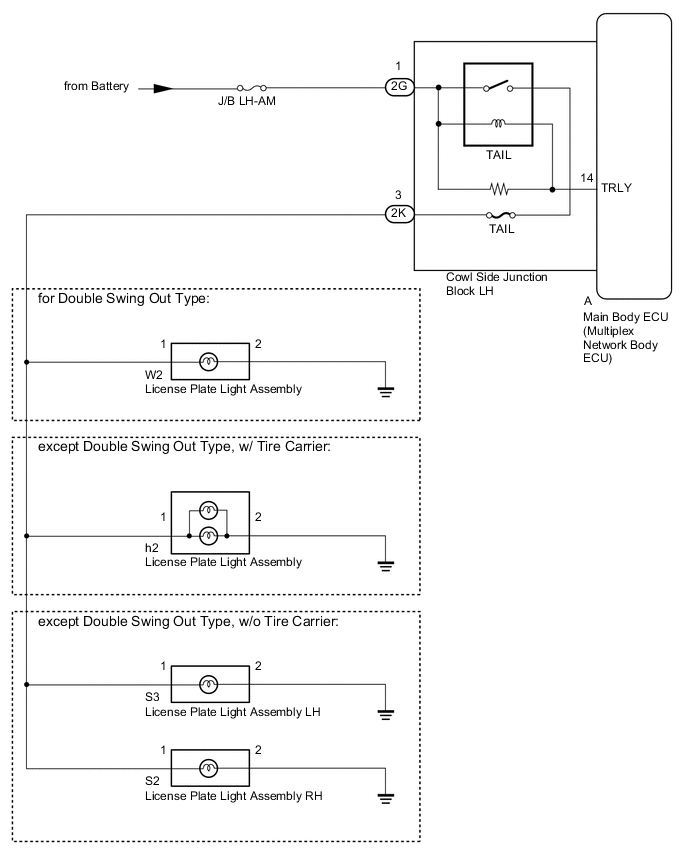
When the light switch TAIL signal is received from the main body ECU (multiplex network body ECU), the license plate light illuminates.
WIRING DIAGRAM
PROCEDURE
-
CHECK HARNESS AND CONNECTOR (COWL SIDE JUNCTION BLOCK LH - BATTERY)
-
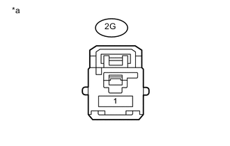
Text in Illustration *a Front view of wire harness connector
(to Cowl Side Junction Block LH)
Disconnect the 2G cowl side junction block LH connector.
-
Measure the voltage according to the value(s) in the table below.
Standard Voltage Tester Connection Condition Specified Condition 2G-1 - Body ground Always 11 to 14 V
NG 
REPAIR OR REPLACE HARNESS OR CONNECTOR
OK 
-
-
CHECK VEHICLE TYPE
-
Check the vehicle type.
Result Result Proceed to for Double Swing Out Type A except Double Swing Out Type, w/ Tire Carrier B except Double Swing Out Type, w/o Tire Carrier C
B 
CHECK HARNESS AND CONNECTOR (LICENSE PLATE LIGHT ASSEMBLY - COWL SIDE JUNCTION BLOCK LH AND BODY GROUND) Click here
C
CHECK HARNESS AND CONNECTOR (LICENSE PLATE LIGHT ASSEMBLY - COWL SIDE JUNCTION BLOCK LH AND BODY GROUND) Click here
A
-
-
CHECK HARNESS AND CONNECTOR (LICENSE PLATE LIGHT ASSEMBLY - COWL SIDE JUNCTION BLOCK LH AND BODY GROUND)
-
Disconnect the 2K cowl side junction block LH connector.
-
Disconnect the W2 light connector.
-
Measure the resistance according to the value(s) in the table below.
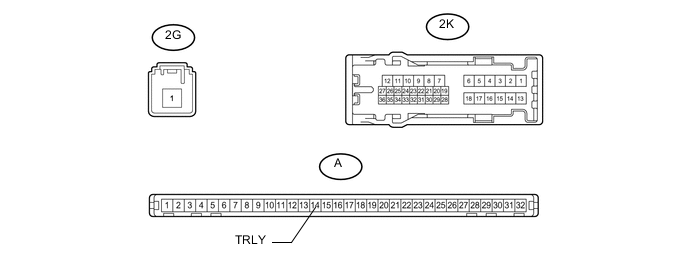
Standard Resistance Tester Connection Condition Specified Condition 2K-3 - W2-1 Always Below 1 Ω W2-2- Body ground W2-1 - Body ground Always 10 kΩ or higher
OK
INSPECT COWL SIDE JUNCTION BLOCK LH Click here
NG
REPAIR OR REPLACE HARNESS OR CONNECTOR
-
-
CHECK HARNESS AND CONNECTOR (LICENSE PLATE LIGHT ASSEMBLY - COWL SIDE JUNCTION BLOCK LH AND BODY GROUND)
-
Disconnect the 2K cowl side junction block LH connector.
-
Disconnect the h2 light connector.
-
Measure the resistance according to the value(s) in the table below.
Standard Resistance Tester Connection Condition Specified Condition 2K-3 - h2-1 Always Below 1 Ω h2-2 - Body ground h2-1 - Body ground Always 10 kΩ or higher
OK
INSPECT COWL SIDE JUNCTION BLOCK LH Click here
NG
REPAIR OR REPLACE HARNESS OR CONNECTOR
-
-
CHECK HARNESS AND CONNECTOR (LICENSE PLATE LIGHT ASSEMBLY - COWL SIDE JUNCTION BLOCK LH AND BODY GROUND)
-
Disconnect the 2K cowl side junction block LH connector.
-
for LH:
-
Disconnect the S3 light connector.
-
Measure the resistance according to the value(s) in the table below.
Standard Resistance Tester Connection Condition Specified Condition 2K-3 - S3-1 Always Below 1 Ω S3-2 - Body ground S3-1 - Body ground Always 10 kΩ or higher
-
-
for RH:
-
Disconnect the S2 light connector.
-
Measure the resistance according to the value(s) in the table below.
Standard Resistance Tester Connection Condition Specified Condition 2K-3 - S2-1 Always Below 1 Ω S2-2 - Body ground S2-1 - Body ground Always 10 kΩ or higher
-
NG
REPAIR OR REPLACE HARNESS OR CONNECTOR
OK
-
-
INSPECT COWL SIDE JUNCTION BLOCK LH
-
for LHD:
-
Remove the cowl side junction block LH Click here.
-
Remove the main body ECU (multiplex network body ECU) from the cowl side junction block LH Click here.
-
-
for RHD:
-
Remove the cowl side junction block LH Click here.
-
Remove the main body ECU (multiplex network body ECU) from the cowl side junction block LH Click here.
-
-
Measure the voltage according to the value(s) in the table below.
Standard Voltage Tester Connection Condition Specified Condition 2K-3 - Battery negative (-) terminal Battery voltage applied between terminals 2G-1 and A-14 (TRLY) 11 to 14 V Battery voltage not applied between terminals 2G-1 and A-14 (TRLY) Below 1 V Result Result Proceed to OK (for LHD) A OK (for RHD) B NG (for LHD) C NG (for RHD) D
A
REPLACE MAIN BODY ECU (MULTIPLEX NETWORK BODY ECU) Click here
B
REPLACE MAIN BODY ECU (MULTIPLEX NETWORK BODY ECU) Click here
C
REPLACE COWL SIDE JUNCTION BLOCK LH Click here
D
REPLACE COWL SIDE JUNCTION BLOCK LH Click here
-