LIGHTING SYSTEM Door Courtesy Light Circuit
DESCRIPTION
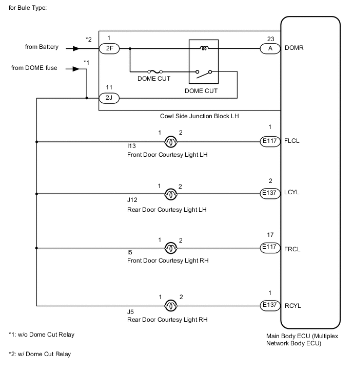
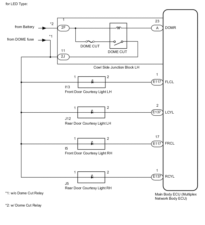
The door courtesy light turns on when the door is opened and turns off when closed.
WIRING DIAGRAM
CAUTION / NOTICE / HINT
Note
-
Inspect the fuses for circuits related to this system before performing the following inspection procedure.
-
If the main body ECU (multiplex network body ECU) is replaced, refer to the Service Bulletin.
PROCEDURE
-
CHECK OPERATION OF DOOR COURTESY LIGHT
-
When a door is opened, check that the following lights do not illuminate.
Result Result Proceed to All door courtesy light does not illuminate A Front door courtesy light LH does not illuminate B Front door courtesy light RH does not illuminate C Rear door courtesy light LH does not illuminate D Rear door courtesy light RH does not illuminate E
B 
INSPECT FRONT DOOR COURTESY LIGHT LH Click here
C
INSPECT FRONT DOOR COURTESY LIGHT RH Click here
D
INSPECT REAR DOOR COURTESY LIGHT LH Click here
E
INSPECT REAR DOOR COURTESY LIGHT RH Click here
A 
-
-
INSPECT COWL SIDE JUNCTION BLOCK LH (DOME CUT RELAY)
-
Remove the cowl side junction block LH.
-
Measure the resistance according to the value(s) in the table below.
Standard Resistance Tester Connection Condition Specified Condition 2F-1 - 2J-11 Battery voltage not applied to terminals 2F-1 and A-23 10 kΩ or higher Battery voltage applied to terminals 2F-1 and A-23 Below 1 Ω
NG 
REPLACE COWL SIDE JUNCTION BLOCK LH (DOME CUT RELAY)
OK
-
-
CHECK HARNESS AND CONNECTOR (DOOR COURTESY LIGHT - BATTERY)
-
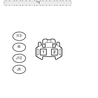
*1 Front view of wire harness connector: (to Door Courtesy Light) Disconnect the I13, I5, J12 and J5 ECU connectors.
-
Measure the voltage according to the value(s) in the table below.
Standard Voltage Tester Connection Switch Condition Specified Condition I13-1 - Body ground Always 11 to 14 V J12-1 - Body ground I5-1 - Body ground J5-1 - Body ground
OK
PROCEED TO NEXT INSPECTION PROCEDURE SHOWN IN PROBLEM SYMPTOMS TABLE Click here
NG
REPAIR OR REPLACE HARNESS OR CONNECTOR
-
-
INSPECT FRONT DOOR COURTESY LIGHT LH
-
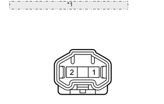
*1 Component without harness connected: (Door Courtesy Light) Remove the door courtesy light connector.
-
Check that the door courtesy light comes on.
OK Measurement Condition Specified Condition Battery positive (+) - Terminal 2
Battery positive (-) - Terminal 1
Light illumination
NG
REPLACE FRONT DOOR COURTESY LIGHT LH Click here
OK
-
-
CHECK HARNESS AND CONNECTOR (MAIN BODY ECU - BODY GROUND)
-
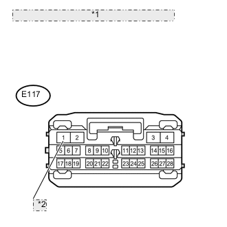
*1 Front view of wire harness connector: (to Main Body ECU) *2 FLCL Disconnect the E117 main body ECU connectors.
-
Measure the voltage according to the value(s) in the table below.
Standard Voltage Tester Connection Condition Specified Condition E117-1 (FLCL) - Body ground Ignition switch ON 11 to 14 V
OK
REPLACE MAIN BODY ECU (MULTIPLEX NETWORK BODY ECU)
NG
REPAIR OR REPLACE HARNESS OR CONNECTOR
-
-
INSPECT FRONT DOOR COURTESY LIGHT RH
-
*1 Component without harness connected: (Door Courtesy Light) Remove the door courtesy light connector.
-
Check that the door courtesy light comes on.
OK Measurement Condition Specified Condition Battery positive (+) - Terminal 2
Battery positive (-) - Terminal 1
Light illumination
NG
REPLACE FRONT DOOR COURTESY LIGHT RH Click here
OK
-
-
CHECK HARNESS AND CONNECTOR (MAIN BODY ECU - BODY GROUND)
-

*1 Front view of wire harness connector: (to Main Body ECU) *2 FRCL Disconnect the E117 main body ECU connectors.
-
Measure the voltage according to the value(s) in the table below.
Standard Voltage Tester Connection Condition Specified Condition E117-17 (FRCL) - Body ground Ignition switch ON 11 to 14 V
OK
REPLACE MAIN BODY ECU (MULTIPLEX NETWORK BODY ECU)
NG
REPAIR OR REPLACE HARNESS OR CONNECTOR
-
-
INSPECT REAR DOOR COURTESY LIGHT LH
-
*1 Component without harness connected: (Door Courtesy Light) Remove the door courtesy light connector.
-
Check that the door courtesy light comes on.
OK Measurement Condition Specified Condition Battery positive (+) - Terminal 2
Battery positive (-) - Terminal 1
Light illumination
NG
REPLACE REAR DOOR COURTESY LIGHT LH Click here
OK
-
-
CHECK HARNESS AND CONNECTOR (MAIN BODY ECU - BODY GROUND)
-
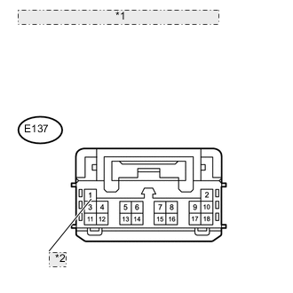
*1 Front view of wire harness connector (to Main Body ECU) *2 LCYL Disconnect the E137 main body ECU connectors.
-
Measure the voltage according to the value(s) in the table below.
Standard Voltage Tester Connection Condition Specified Condition E137-2 (LCYL) - Body ground Ignition switch ON 11 to 14 V
OK
REPLACE MAIN BODY ECU (MULTIPLEX NETWORK BODY ECU)
NG
REPAIR OR REPLACE HARNESS OR CONNECTOR
-
-
INSPECT REAR DOOR COURTESY LIGHT RH
-
*1 Component without harness connected: (Door Courtesy Light) Remove the door courtesy light connector.
-
Check that the door courtesy light comes on.
OK Measurement Condition Specified Condition Battery positive (+) - Terminal 2
Battery positive (-) - Terminal 1
Light illumination
NG
REPLACE REAR DOOR COURTESY LIGHT RH Click here
OK
-
-
CHECK HARNESS AND CONNECTOR (MAIN BODY ECU - BODY GROUND)
-
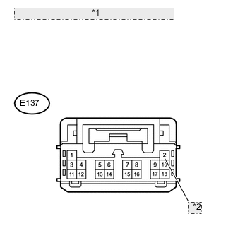
*1 Front view of wire harness connector (to Main Body ECU) *2 RCYL Disconnect the E137 main body ECU connectors.
-
Measure the voltage according to the value(s) in the table below.
Standard Voltage Tester Connection Condition Specified Condition E137-1 (RCYL) - Body ground Ignition switch ON 11 to 14 V
OK
REPLACE MAIN BODY ECU (MULTIPLEX NETWORK BODY ECU)
NG
REPAIR OR REPLACE HARNESS OR CONNECTOR
-