LIGHTING SYSTEM Door Illumination Circuit
DESCRIPTION
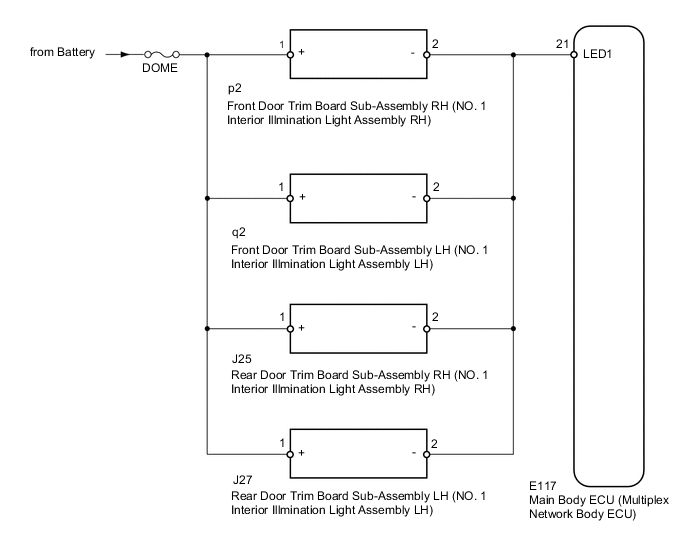
The rear door illumination is controlled by the main body ECU.
WIRING DIAGRAM
CAUTION / NOTICE / HINT
Note
-
Inspect the fuses for circuits related to this system before performing the following inspection procedure.
-
If the main body ECU (multiplex network body ECU) is replaced, refer to the Service Bulletin.
PROCEDURE
-
PERFORM ACTIVE TEST USING GTS (INTERIOR ILLUMINATION LIGHT1)
-
Operate the GTS according to the steps on the display and select "Active Test".
Main Body Tester Display Test Part Control Range Diagnostic Note Interior Illumination Light1 door illumination light* OFF or ON - *: 15 seconds after turning the engine switch off, check the operation once the rear door illumination turns off.
OK Rear door illumination illuminates. Result Result Proceed OK A NG (Front Door LH Side) B NG (Front Door RH Side) C NG (Rear Door LH Side) D NG (Rear Door RH Side) E
A 
PROCEED TO NEXT SUSPECTED AREA SHOWN IN PROBLEM SYMPTOMS TABLE Click here
C 
CHECK HARNESS AND CONNECTOR (MAIN BODY ECU - FRONT DOOR TRIM BOARD SUB-ASSEMBLY RH) Click here
D
CHECK HARNESS AND CONNECTOR (MAIN BODY ECU - REAR DOOR TRIM BOARD SUB-ASSEMBLY LH) Click here
E
CHECK HARNESS AND CONNECTOR (MAIN BODY ECU - REAR DOOR TRIM BOARD SUB-ASSEMBLY RH) Click here
B 
-
-
CHECK HARNESS AND CONNECTOR (MAIN BODY ECU - FRONT DOOR TRIM BOARD SUB-ASSEMBLY LH)
-
Remove the front door trim board sub-assembly LH.
-
Remove the DOME fuse from cowl side junction block LH.
-
Remove the main body ECU (multiplex network body ECU) from the junction block assembly LH.
-
Measure the resistance according to the value(s) in the table below.
Standard Resistance Tester Connection Condition Specified Condition E117-21 (LED1) - q2-2 (-) Always Below 1 Ω 2 (DOME fuse holder) - q2-1 (+) Always Below 1 Ω E117-21 (LED1) - Body ground Always 10 kΩ or higher 2 (DOME fuse holder) or q2-1 (+) - Body ground Always 10 kΩ or higher
NG
REPAIR OR REPLACE HARNESS OR CONNECTOR
OK
-
-
INSPECT FRONT DOOR TRIM BOARD SUB-ASSEMBLY LH
-
Temporarily replace the eront door trim board sub-assembly LH with a new or normally functioning one.
OK The illumination illuminates normally.
OK
END (FRONT DOOR TRIM BOARD SUB-ASSEMBLY LH IS DEFECTIVE)
NG
REPLACE MAIN BODY ECU (MULTIPLEX NETWORK BODY ECU)
-
-
CHECK HARNESS AND CONNECTOR (MAIN BODY ECU - FRONT DOOR TRIM BOARD SUB-ASSEMBLY RH)
-
Remove the front door trim board sub-assembly RH.
-
Remove the DOME fuse from cowl side junction block LH.
-
Remove the main body ECU (multiplex network body ECU) from the junction block assembly LH.
-
Measure the resistance according to the value(s) in the table below.
Standard Resistance Tester Connection Condition Specified Condition E117-21 (LED1) - p2-2 (-) Always Below 1 Ω 2 (DOME fuse holder) - p2-1 (+) Always Below 1 Ω E117-21 (LED1) - Body ground Always 10 kΩ or higher 2 (DOME fuse holder) or p2-1 (+) - Body ground Always 10 kΩ or higher
NG
REPAIR OR REPLACE HARNESS OR CONNECTOR
OK
-
-
INSPECT FRONT DOOR TRIM BOARD SUB-ASSEMBLY RH
-
Temporarily replace the front door trim board sub-assembly RH with a new or normally functioning one.
OK The illumination illuminates normally.
OK
END (FRONT DOOR TRIM BOARD SUB-ASSEMBLY RH IS DEFECTIVE)
NG
REPLACE MAIN BODY ECU (MULTIPLEX NETWORK BODY ECU)
-
-
CHECK HARNESS AND CONNECTOR (MAIN BODY ECU - REAR DOOR TRIM BOARD SUB-ASSEMBLY LH)
-
Remove the rear door trim board sub-assembly LH.
-
Remove the DOME fuse from cowl side junction block LH.
-
Remove the main body ECU (multiplex network body ECU) from the junction block assembly LH.
-
Measure the resistance according to the value(s) in the table below.
Standard Resistance Tester Connection Condition Specified Condition E117-21 (LED1) - J27-2 (-) Always Below 1 Ω 2 (DOME fuse holder) - J27-1 (+) Always Below 1 Ω E117-21 (LED1) - Body ground Always 10 kΩ or higher 2 (DOME fuse holder) or J27-1 (+) - Body ground Always 10 kΩ or higher
NG
REPAIR OR REPLACE HARNESS OR CONNECTOR
OK
-
-
INSPECT REAR DOOR TRIM BOARD SUB-ASSEMBLY LH
-
Temporarily replace the rear door trim board sub-assembly LH with a new or normally functioning one.
OK The illumination illuminates normally.
OK
END (REAR DOOR TRIM BOARD SUB-ASSEMBLY LH IS DEFECTIVE)
NG
REPLACE MAIN BODY ECU (MULTIPLEX NETWORK BODY ECU)
-
-
CHECK HARNESS AND CONNECTOR (MAIN BODY ECU - REAR DOOR TRIM BOARD SUB-ASSEMBLY RH)
-
Remove the rear door trim board sub-assembly RH.
-
Remove the DOME fuse from cowl side junction block LH.
-
Remove the main body ECU (multiplex network body ECU) from the junction block assembly LH.
-
Measure the resistance according to the value(s) in the table below.
Standard Resistance Tester Connection Condition Specified Condition E117-21 (LED1) - J25-2 (-) Always Below 1 Ω 2 (DOME fuse holder) - J25-1 (+) Always Below 1 Ω E117-21 (LED1) - Body ground Always 10 kΩ or higher 2 (DOME fuse holder) or J25-1 (+) - Body ground Always 10 kΩ or higher
NG
REPAIR OR REPLACE HARNESS OR CONNECTOR
OK
-
-
INSPECT REAR DOOR TRIM BOARD SUB-ASSEMBLY RH
-
Temporarily replace the rear door trim board sub-assembly RH with a new or normally functioning one.
OK The illumination illuminates normally.
OK
END (REAR DOOR TRIM BOARD SUB-ASSEMBLY RH IS DEFECTIVE)
NG
REPLACE MAIN BODY ECU (MULTIPLEX NETWORK BODY ECU)
-