LIGHTING SYSTEM Door Courtesy Switch Circuit
DESCRIPTION
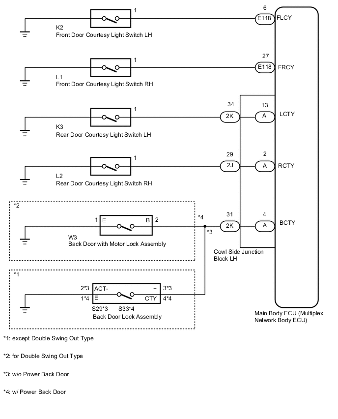
The main body ECU receives a door open/closed signal from each door courtesy light switch.
WIRING DIAGRAM
PROCEDURE
-
READ VALUE USING GTS (DOOR COURTESY LIGHT SWITCH)
-
Using the GTS, read the Data List Click here.
Main Body Tester Display Measurement Item/Range Normal Condition Diagnostic Note D Door Courtesy SW Front door courtesy light switch LH signal / ON or OFF ON: Front door courtesy light switch LH on
OFF: Front door courtesy light switch LH off
- P Door Courtesy SW Front door courtesy light switch RH signal / ON or OFF ON: Front door courtesy light switch RH on
OFF: Front door courtesy light switch RH off
- RL Door Courtesy SW Rear door courtesy light switch LH signal / ON or OFF ON: Rear door courtesy light switch LH on
OFF: Rear door courtesy light switch LH off
- RR Door Courtesy SW Rear door courtesy light switch RH signal / ON or OFF ON: Rear door courtesy light switch RH on
OFF: Rear door courtesy light switch RH off
- Back Door Courtesy SW Back door courtesy light switch signal / ON or OFF ON: Back door courtesy light switch on
OFF: Back door courtesy light switch off
- OK Door courtesy light switch on/off
OK 
PROCEED TO NEXT SUSPECTED AREA SHOWN IN PROBLEM SYMPTOMS TABLE Click here
NG 
-
-
CHECK DOOR COURTESY LIGHT SWITCH
Result Result Proceed to Front door courtesy light switch LH does not operate A Front door courtesy light switch RH does not operate B Rear door courtesy light switch LH does not operate C Rear door courtesy light switch RH does not operate D Back door courtesy light switch does not operate E
B 
INSPECT FRONT DOOR COURTESY LIGHT SWITCH RH Click here
C
INSPECT REAR DOOR COURTESY LIGHT SWITCH LH Click here
D
INSPECT REAR DOOR COURTESY LIGHT SWITCH RH Click here
E
INSPECT VEHICLE TYPE Click here
A
-
INSPECT FRONT DOOR COURTESY LIGHT SWITCH LH
-
Remove the front door courtesy light switch LH Click here.
-
Inspect the front door courtesy light switch LH Click here.
NG
REPLACE FRONT DOOR COURTESY LIGHT SWITCH LH Click here
OK
-
-
CHECK HARNESS AND CONNECTOR (FRONT DOOR COURTESY LIGHT SWITCH LH - MAIN BODY ECU (MULTIPLEX NETWORK BODY ECU))
-
Disconnect the K2 front door courtesy light switch LH connector.
-
Disconnect the E118 main body ECU connector.
-
Measure the resistance according to the value(s) in the table below.
Standard Resistance Tester Connection Condition Specified Condition K2-1 - E118-6 (FLCY) Always Below 1 Ω K2-1 - Body ground Always 10 kΩ or higher
OK
REPLACE MAIN BODY ECU (MULTIPLEX NETWORK BODY ECU)
NG
REPAIR OR REPLACE HARNESS OR CONNECTOR
-
-
INSPECT FRONT DOOR COURTESY LIGHT SWITCH RH
-
Remove the front door courtesy light switch RH Click here.
-
Inspect the front door courtesy light switch RH Click here.
NG
REPLACE FRONT DOOR COURTESY LIGHT SWITCH RH Click here
OK
-
-
CHECK HARNESS AND CONNECTOR (FRONT DOOR COURTESY LIGHT SWITCH RH - MAIN BODY ECU (MULTIPLEX NETWORK BODY ECU))
-
Disconnect the L1 front door courtesy light switch RH switch connector.
-
Disconnect the E118 main body ECU connector.
-
Measure the resistance according to the value(s) in the table below.
Standard Resistance Tester Connection Condition Specified Condition L1-1 - E118-27 (FRCY) Always Below 1 Ω L1-1 - Body ground Always 10 kΩ or higher
OK
REPLACE MAIN BODY ECU (MULTIPLEX NETWORK BODY ECU)
NG
REPAIR OR REPLACE HARNESS OR CONNECTOR
-
-
INSPECT REAR DOOR COURTESY LIGHT SWITCH LH
-
Remove the rear door courtesy light switch LH Click here.
-
Inspect the rear door courtesy light switch LH Click here.
NG
REPLACE REAR DOOR COURTESY LIGHT SWITCH LH Click here
OK
-
-
CHECK HARNESS AND CONNECTOR (REAR DOOR COURTESY LIGHT SWITCH LH - COWL SIDE JUNCTION BLOCK LH)
-
Disconnect the 2K cowl side junction block LH connector.
-
Disconnect the K3 rear door courtesy light switch LH connector.
-
Measure the resistance according to the value(s) in the table below.
Standard Resistance Tester Connection Condition Specified Condition K3-1 - 2K-34 (LCTY) Always Below 1 Ω K3-1 - Body ground Always 10 kΩ or higher
OK
CHECK COWL SIDE JUNCTION BLOCK LH Click here
NG
REPAIR OR REPLACE HARNESS OR CONNECTOR
-
-
INSPECT REAR DOOR COURTESY LIGHT SWITCH RH
-
Remove the rear door courtesy light switch RH Click here.
-
Inspect the rear door courtesy light switch RH Click here.
NG
REPLACE REAR DOOR COURTESY LIGHT SWITCH RH Click here
OK
-
-
CHECK HARNESS AND CONNECTOR (REAR DOOR COURTESY LIGHT SWITCH RH - COWL SIDE JUNCTION BLOCK LH)
-
Disconnect the L2 rear door courtesy light switch RH connector.
-
Disconnect the 2J cowl side junction block LH connector.
-
Measure the resistance according to the value(s) in the table below.
Standard Resistance Tester Connection Condition Specified Condition L2-1 - 2J-29 (RCTY) Always Below 1 Ω L2-1 - Body ground Always 10 kΩ or higher
OK
CHECK COWL SIDE JUNCTION BLOCK LH Click here
NG
REPAIR OR REPLACE HARNESS OR CONNECTOR
-
-
INSPECT VEHICLE TYPE
-
Check the vehicle type.
Result Result Proceed to for Double Swing Out Type A except Double Swing Out Type B
B
INSPECT BACK DOOR LOCK ASSEMBLY Click here
A
-
-
INSPECT BACK DOOR WITH MOTOR LOCK ASSEMBLY
-
Remove the back door with motor lock assembly Click here.
-
Inspect the back door with motor lock assembly Click here.
NG
REPLACE BACK DOOR WITH MOTOR LOCK ASSEMBLY Click here
OK
-
-
CHECK HARNESS AND CONNECTOR (BACK DOOR WITH MOTOR LOCK ASSEMBLY - COWL SIDE JUNCTION BLOCK LH AND BODY GROUND)
-
Disconnect 2K cowl side junction block LH connector.
-
Disconnect W3 back door with motor lock connector.
-
Measure the resistance according to the value(s) in the table below.
Standard Resistance Tester Connection Condition Specified Condition W3-2 (B) - 2K-31 (BCTY) Always Below 1 Ω W3-1 (E) - Body ground W3-2 (B) - Body ground Always 10 kΩ or higher
OK
CHECK COWL SIDE JUNCTION BLOCK LH Click here
NG
REPAIR OR REPLACE HARNESS OR CONNECTOR
-
-
INSPECT BACK DOOR LOCK ASSEMBLY
-
Remove the back door lock Click here.
-
Inspect the back door lock Click here.
NG
REPLACE BACK DOOR LOCK ASSEMBLY Click here
OK
-
-
CHECK HARNESS AND CONNECTOR (BACK DOOR LOCK ASSEMBLY - COWL SIDE JUNCTION BLOCK LH AND BODY GROUND)
-
Disconnect the 2K cowl side junction block LH connector.
-
w/o Power Back Door:
-
Disconnect the S29 back door lock connector.
-
Measure the resistance according to the value(s) in the table below.
Standard Resistance Tester Connection Condition Specified Condition S29-3 (+) - 2K-31 (BCTY) Always Below 1 Ω S29-2 (ACT-) - Body ground S29-3 (+) - Body ground Always 10 kΩ or higher
-
-
w/ Power Back Door:
-
Disconnect the S33 back door lock connector.
-
Measure the resistance according to the value(s) in the table below.
Standard Resistance Tester Connection Condition Specified Condition S33-4 (CTY) - 2K-31 (BCTY) Always Below 1 Ω S33-1 (E) - Body ground S33-4 (CTY) - Body ground Always 10 kΩ or higher
-
OK
CHECK COWL SIDE JUNCTION BLOCK LH Click here
NG
REPAIR OR REPLACE HARNESS OR CONNECTOR
-
-
CHECK COWL SIDE JUNCTION BLOCK LH
-
Remove the cowl side junction block LH.
-
Remove the main body ECU from the cowl side junction block LH
-
Measure the resistance according to the value(s) in the table below.
Standard Resistance Tester Connection Condition Specified Condition 2K-34 - A-13 Always Below 1 Ω 2K-34 - Body ground Always 10 kΩ or higher
OK
REPLACE MAIN BODY ECU (MULTIPLEX NETWORK BODY ECU)
NG
REPLACE COWL SIDE JUNCTION BLOCK LH
-
-
CHECK COWL SIDE JUNCTION BLOCK LH
-
Remove the cowl side junction block LH.
-
Remove the main body ECU from the cowl side junction block LH
-
Measure the resistance according to the value(s) in the table below.
Standard Resistance Tester Connection Condition Specified Condition 2J-29 - A-2 Always Below 1 Ω 2J-29 - Body ground Always 10 kΩ or higher
OK
REPLACE MAIN BODY ECU (MULTIPLEX NETWORK BODY ECU)
NG
REPLACE COWL SIDE JUNCTION BLOCK LH
-
-
CHECK COWL SIDE JUNCTION BLOCK LH
-
Remove the cowl side junction block LH.
-
Remove the main body ECU from the cowl side junction block LH
-
Measure the resistance according to the value(s) in the table below.
Standard Resistance Tester Connection Condition Specified Condition 2K-31 - A-4 Always Below 1 Ω 2K-31 - Body ground Always 10 kΩ or higher
OK
REPLACE MAIN BODY ECU (MULTIPLEX NETWORK BODY ECU)
NG
REPLACE COWL SIDE JUNCTION BLOCK LH
-