LIGHTING SYSTEM Light Control Switch Circuit
DESCRIPTION
The main body ECU receives light control switch, dimmer switch and front fog light switch information signals from the headlight dimmer switch.
WIRING DIAGRAM
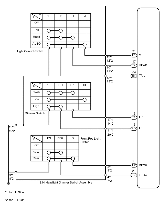
PROCEDURE
-
READ VALUE USING INTELLIGENT TESTER (HEADLIGHT DIMMER SWITCH)
-
Operate the intelligent tester according to the display and select the "Data List".
Main Body Tester Display Measurement Item/Range Normal Condition Diagnostic Note Dimmer SW Dimmer switch signal/ON or OFF ON: Dimmer switch on
OFF: Dimmer switch off
- Passing Light SW Passing light switch signal/ON or OFF ON: Passing light switch on
OFF: Passing light switch off
- Front Fog Light SW Front fog light switch signal/ON or OFF ON: Front fog light switch on
OFF: Front fog light switch off
- Rear Fog Light SW Rear fog light switch signal/ON or OFF ON: Rear fog light switch on
OFF: Rear fog light switch off
- Auto Light SW Auto light switch signal/ON or OFF ON: Auto light switch on
OFF: Auto light switch off
- Head Light SW (Head) Headlight switch signal/ON or OFF ON: Headlight switch (Head) on
OFF: Headlight switch (Head) off
- Head Light SW (Tail) Taillight switch signal/ON or OFF ON: Headlight switch (Tail) on
OFF: Headlight switch (Tail) off
- OK When combination light switch operation is performed, the result will be the same as above.
OK 
PROCEED TO NEXT CIRCUIT INSPECTION SHOWN IN PROBLEM SYMPTOMS TABLE Click here
NG 
-
-
INSPECT HEADLIGHT DIMMER SWITCH ASSEMBLY
-
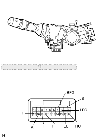
for LH Side *1 Component without harness connected: (Headlight Dimmer Switch Assembly) Remove the headlight dimmer switch Click here.
-
for LH Side:
-
Measure the resistance according to the value(s) in the table below.
Standard Resistance Tester Connection Switch Condition Specified Condition 18 (T) - 12 (EL) Light control switch tail Below 1 Ω 20 (H) - 12 (EL) Light control switch head 18 (T) - 12 (EL) 19 (A) - 12 (EL) Light control switch AUTO 4 (BFG) - 3 (LFG) Front fog light switch on 2 (B) - 3 (LFG) Rear fog light switch on 17 (HF) - 12 (EL) Dimmer switch flash 11 (HU) - 12 (EL) Dimmer switch hi beam
-
-
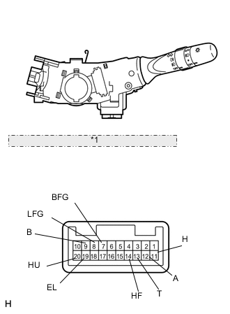
for RH Side *1 Component without harness connected: (Headlight Dimmer Switch Assembly) for RH Side:
-
Measure the resistance according to the value(s) in the table below.
Standard Resistance Tester Connection Condition Specified Condition 13 (T) - 19 (EL) Light control switch tail Below 1 Ω 11 (H) - 19 (EL) Light control switch head 13 (T) - 19 (EL) 12 (AUTO) - 19 (EL) Light control switch AUTO 7 (BFG) - 8 (LFG) Front fog light switch on 9 (B) - 8 (LFG) Rear fog light switch on 14 (HF) - 19 (EL) Dimmer switch flash 20 (HU) - 19 (EL) Dimmer switch hi beam
-
NG
REPLACE HEADLIGHT DIMMER SWITCH ASSEMBLY Click here
OK
-
-
CHECK HARNESS AND CONNECTOR (HEADLIGHT DIMMER SWITCH - MAIN BODY ECU AND BODY GROUND)
-
Disconnect the E14 switch connector.
-
for LH Side:
-
Disconnect the E1, E2 and 2D ECU connectors.
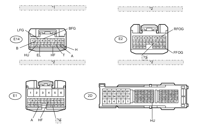
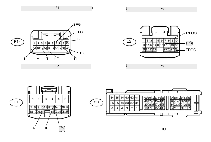
*1 Front view of wire harness connector: (to Headlight Dimmer Switch Assembly) *2 Front view of wire harness connector: (to Main Body ECU) *3 HEAD *4 TAIL -
Measure the resistance according to the value(s) in the table below.
Standard Resistance Tester Connection Condition Specified Condition E14-4 (BFG) - E2-28 (FFOG) Always Below 1 Ω E14-2 (B) - E2-9 (RFGO) E14-19 (A) - E1-21 (A) E14-20 (H) - E2-17 (HEAD) E14-18 (T) - E1-23 (TAIL) E14-17 (HF) - E1-13 (HF) E14-11 (HU) - 2D-13 (HU) E14-12 (EL) - Body ground E14-3 (LFG) - Body ground E14-4 (BFG) - Body ground Always 10 kΩ or higher E14-2 (B) - Body ground E14-19 (A) - Body ground E14-20 (H) - Body ground E14-18 (T) - Body ground E14-17 (HF) - Body ground E14-11 (HU) - Body ground
-
-
for RH Side:
-
Disconnect the E1, E2 and 2D ECU connectors.
*1 Front view of wire harness connector: (to Headlight Dimmer Switch Assembly) *2 Front view of wire harness connector: (to Main Body ECU) *3 HEAD *4 TAIL -
Measure the resistance according to the value(s) in the table below.
Standard Resistance Tester Connection Condition Specified Condition E14-7 (BFG) - E2-28 (FFOG) Always Below 1 Ω E14-9 (B) - E2-9 (RFOG) E14-12 (A) - E1-21 (A) E14-11 (H) - E2-17 (HEAD) E14-13 (T) - E1-23 (TAIL) E14-14 (HF) - E1-13 (HF) E14-20 (HU) - 2D-13 (HU) E14-19 (EL) - Body ground E14-8 (LFG) - Body ground E14-7 (BFG) - Body ground Always 10 kΩ or higher E14-9 (B) - Body ground E14-12 (A) - Body ground E14-11 (H) - Body ground E14-13 (T) - Body ground E14-14 (HF) - Body ground E14-20 (HU) - Body ground
-
OK
REPLACE MAIN BODY ECU
NG
REPAIR OR REPLACE HARNESS OR CONNECTOR
-