LIGHTING SYSTEM Back-up Light Circuit
DESCRIPTION
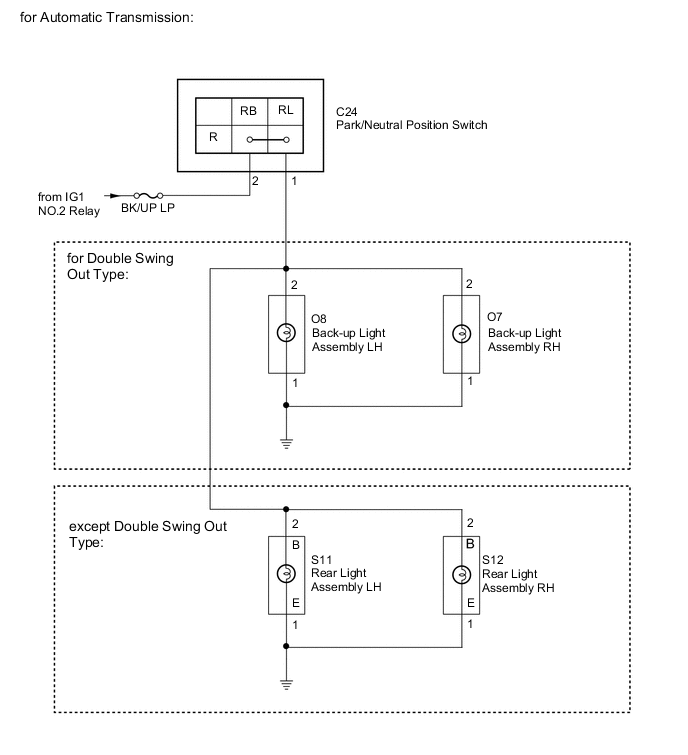
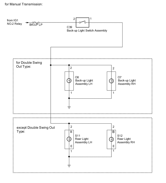
The park/neutral position switch turns on when the shift lever is moved to R, causing the back-up lights to illuminate.
WIRING DIAGRAM
PROCEDURE
-
INSPECT FUSE (BK/UP LP FUSE)
-
Remove the BK/UP LP fuse from the main body ECU.
-
Measure the resistance according to the value(s) in the table below.
Standard Resistance Tester Connection Condition Specified Condition BK/UP LP fuse Always Below 1 Ω
NG 
REPLACE FUSE
OK 
-
-
CHECK VEHICLE TYPE
-
Check the vehicle type.
Result Result Proceed to for Automatic Transmission A for Manual Transmission B
B 
INSPECT BACK-UP LIGHT SWITCH Click here
A
-
-
INSPECT PARK/NEUTRAL POSITION SWITCH
-
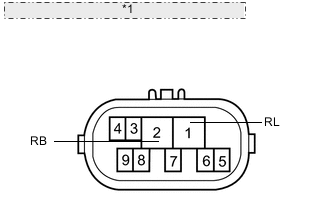
*1 Component without harness connected: (Park/Neutral Position Switch) Remove the park/neutral position switch.
-
for A750F Automatic Transmission: Click here
-
for AB60F Automatic Transmission: Click here
-
-
Measure the resistance according to the value(s) in the table below.
Standard Resistance Tester Connection Condition Specified Condition 2 (RB) - 1 (RL) Shift lever in R Below 1 Ω 2 (RB) - 1 (RL) Shift lever not in R 10 kΩ or higher Result Result Proceed to OK A NG (for A750F Automatic Transmission) B NG (for AB60F Automatic Transmission) C
B
REPLACE PARK/NEUTRAL POSITION SWITCH Click here
C
REPLACE PARK/NEUTRAL POSITION SWITCH Click here
A
-
-
CHECK HARNESS AND CONNECTOR (PARK/NEUTRAL POSITION SWITCH - BATTERY)
-
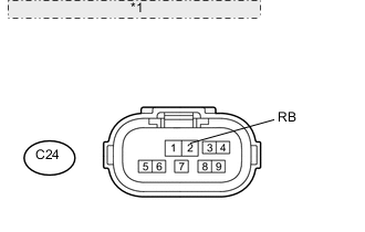
*1 Front view of wire harness connector: (to Park/Neutral Position Switch) Disconnect the C24 park/neutral position switch connector.
-
Measure the voltage according to the value(s) in the table below.
Standard Voltage Tester Connection Switch Condition Specified Condition C24-2 (RB) - Body ground Ignition switch ON 11 to 14 V
NG
REPAIR OR REPLACE HARNESS OR CONNECTOR
OK
-
-
CHECK VEHICLE TYPE
-
Check the vehicle type.
Result Result Proceed to for Double Swing Out Type A except Double Swing Out Type B
B
CHECK HARNESS AND CONNECTOR (PARK/NEUTRAL POSITION SWITCH - REAR LIGHT AND BODY GROUND) Click here
A
-
-
CHECK HARNESS AND CONNECTOR (PARK/NEUTRAL POSITION SWITCH - BACK-UP LIGHT AND BODY GROUND)
-
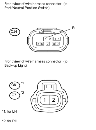
Disconnect the C24 park/neutral position switch connector.
-
for LH:
-
Disconnect the O8 light connector.
-
Measure the resistance according to the value(s) in the table below.
Standard Resistance Tester Connection Condition Specified Condition C24-1 (RL) - O8-2 Always Below 1 Ω O8-1 - Body ground O8-2 - Body ground Always 10 kΩ or higher
-
-
for RH:
-
Disconnect the O7 light connector.
-
Measure the resistance according to the value(s) in the table below.
Standard Resistance Tester Connection Condition Specified Condition C24-1 (RL) - O7-2 Always Below 1 Ω O7-1 - Body ground O7-2 - Body ground Always 10 kΩ or higher
-
OK
PROCEED TO NEXT INSPECTION PROCEDURE SHOWN IN PROBLEM SYMPTOMS TABLE Click here
NG
REPAIR OR REPLACE HARNESS OR CONNECTOR
-
-
CHECK HARNESS AND CONNECTOR (PARK/NEUTRAL POSITION SWITCH - REAR LIGHT AND BODY GROUND)
-
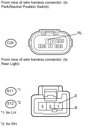
Disconnect the C24 park/neutral position switch connector.
-
for LH:
-
Disconnect the S11 light connector.
-
Measure the resistance according to the value(s) in the table below.
Standard Resistance Tester Connection Condition Specified Condition C24-1 (RL) - S11-2 (B) Always Below 1 Ω S11-1 (E) - Body ground S11-2 (B) - Body ground Always 10 kΩ or higher
-
-
for RH:
-
Disconnect the S12 light connector.
-
Measure the resistance according to the value(s) in the table below.
Standard Resistance Tester Connection Condition Specified Condition C24-1 (RL) - S12-2 (B) Always Below 1 Ω S12-1 (E) - Body ground S12-2 (B) - Body ground Always 10 kΩ or higher
-
OK
PROCEED TO NEXT INSPECTION PROCEDURE SHOWN IN PROBLEM SYMPTOMS TABLE Click here
NG
REPAIR OR REPLACE HARNESS OR CONNECTOR
-
-
INSPECT BACK-UP LIGHT SWITCH
-
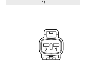
*1 Component without harness connected: (Back-up Light Switch) Remove the back-up light switch Click here.
-
Measure the resistance according to the value(s) in the table below.
Standard Resistance Tester Connection Switch Condition Specified Condition 1 - 2 On (pushed) Below 1 Ω 1 - 2 Off (released) 10 kΩ or higher
NG
REPLACE BACK-UP LIGHT SWITCH ASSEMBLY Click here
OK
-
-
CHECK HARNESS AND CONNECTOR (BACK-UP LIGHT SWITCH - BATTERY)
-
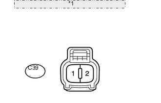
*1 Front view of wire harness connector: (to Back-up Light Switch) Disconnect the C39 back-up light switch connector.
-
Measure the voltage according to the value(s) in the table below.
Standard Voltage Tester Connection Switch Condition Specified Condition C39-2 - Body ground Ignition switch ON 11 to 14 V
NG
REPAIR OR REPLACE HARNESS OR CONNECTOR
OK
-
-
CHECK VEHICLE TYPE
-
Check the vehicle type.
Result Result Proceed to for Double Swing Out Type A except Double Swing Out Type B
B
CHECK HARNESS OR CONNECTOR (BACK-UP LIGHT SWITCH - REAR LIGHT AND BODY GROUND) Click here
A
-
-
CHECK HARNESS AND CONNECTOR (BACK-UP LIGHT SWITCH - BACK-UP LIGHT AND BODY GROUND)
-
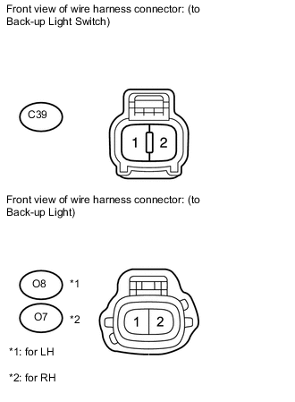
Disconnect the C39 back-up light switch connector.
-
for LH:
-
Disconnect the O8 light connector.
-
Measure the resistance according to the value(s) in the table below.
Standard Resistance Tester Connection Condition Specified Condition C39-1 - O8-2 Always Below 1 Ω O8-1 - Body ground O8-2 - Body ground Always 10 kΩ or higher
-
-
for RH:
-
Disconnect the O7 light connector.
-
Measure the resistance according to the value(s) in the table below.
Standard Resistance Tester Connection Condition Specified Condition C39-1 - O7-2 Always Below 1 Ω O7-1 - Body ground O7-2 - Body ground Always 10 kΩ or higher
-
OK
PROCEED TO NEXT INSPECTION PROCEDURE SHOWN IN PROBLEM SYMPTOMS TABLE Click here
NG
REPAIR OR REPLACE HARNESS OR CONNECTOR
-
-
CHECK HARNESS OR CONNECTOR (BACK-UP LIGHT SWITCH - REAR LIGHT AND BODY GROUND)
-
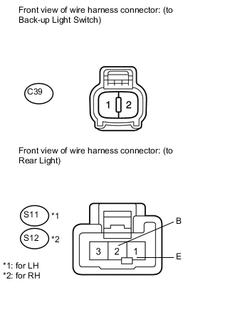
Disconnect the C39 back-up light switch connector.
-
for LH:
-
Disconnect the S11 light connector.
-
Measure the resistance according to the value(s) in the table below.
Standard Resistance Tester Connection Condition Specified Condition C39-1 - S11-2 (B) Always Below 1 Ω S11-1 (E) - Body ground S11-2 (B) - Body ground Always 10 kΩ or higher
-
-
for RH:
-
Disconnect the S12 light connector.
-
Measure the resistance according to the value(s) in the table below.
Standard Resistance Tester Connection Condition Specified Condition C39-1 - S12-2 (B) Always Below 1 Ω S12-1 (E) - Body ground 12-2 (B) - Body ground Always 10 kΩ or higher
-
OK
PROCEED TO NEXT INSPECTION PROCEDURE SHOWN IN PROBLEM SYMPTOMS TABLE Click here
NG
REPAIR OR REPLACE HARNESS OR CONNECTOR
-