LIGHTING SYSTEM Headlight Dimmer Switch Circuit
DESCRIPTION
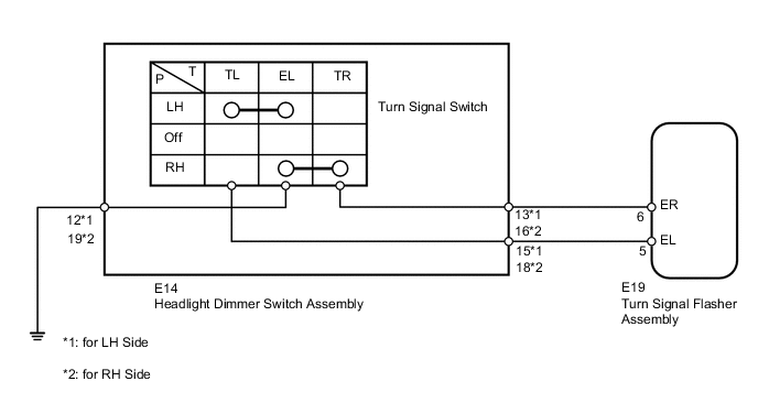
The turn signal flasher receives a turn signal light information signal from the headlight dimmer switch.
WIRING DIAGRAM
PROCEDURE
-
INSPECT HEADLIGHT DIMMER SWITCH (TURN SIGNAL SWITCH)
-
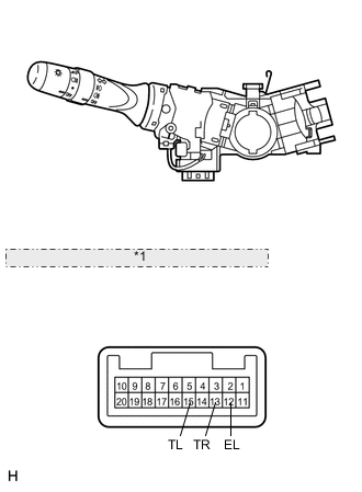
for LH Side *1 Component without harness connected: (Headlight Dimmer Switch Assembly) Remove the headlight dimmer switch Click here.
-
for LH Side:
Measure the resistance according to the value(s) in the table below.
Standard Resistance Tester Connection Switch Condition Specified Condition 13 (TR) - 12 (EL) Turn signal switch right turn Below 1 Ω Turn signal switch off 10 kΩ or higher 15 (TL) - 12 (EL) Turn signal switch left turn Below 1 Ω Turn signal switch off 10 kΩ or higher -
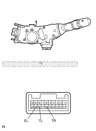
for RH Side *1 Component without harness connected: (Headlight Dimmer Switch Assembly) for RH Side:
Measure the resistance according to the value(s) in the table below.
Standard Resistance Tester Connection Switch Condition Specified Condition 16 (TR) - 19 (EL) Turn signal switch right turn Below 1 Ω Turn signal switch off 10 kΩ or higher 18 (TL) - 19 (EL) Turn signal switch left turn Below 1 Ω Turn signal switch off 10 kΩ or higher
NG 
REPLACE HEADLIGHT DIMMER SWITCH Click here
OK 
-
-
CHECK HARNESS AND CONNECTOR (HEADLIGHT DIMMER SWITCH - TURN SIGNAL FLASHER AND BODY GROUND)
-
Disconnect the E14 switch connector.
-
Disconnect the E19 relay connector.
-
for LH Side:
Measure the resistance according to the value(s) in the table below.
Standard Resistance Tester Connection Condition Specified Condition E14-13 (TR) - E19-6 (ER) Always Below 1 Ω E14-15 (TL) - E19-5 (EL) E14-12 (EL) - Body ground E14-13 (TR) - Body ground Always 10 kΩ or higher E14-15 (TL) - Body ground -
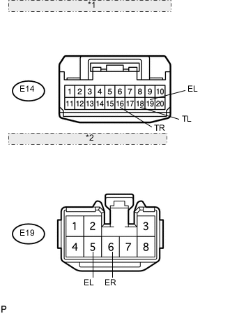
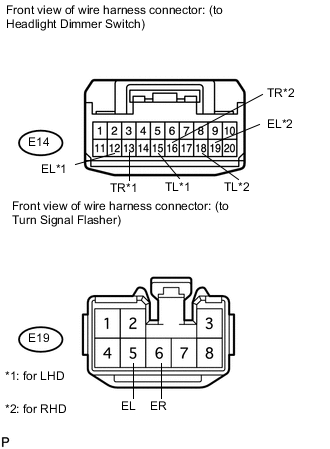
*1 Front view of wire harness connector: (to Headlight Dimmer Switch Assembly) *2 Front view of wire harness connector: (to Turn Signal Flasher Assembly) for RH Side:
Measure the resistance according to the value(s) in the table below.
Standard Resistance Tester Connection Condition Specified Condition E14-16 (TR) - E19-6 (ER) Always Below 1 Ω E14-18 (TL) - E19-5 (EL) E14-19 (EL) - Body ground E14-16 (TR) - Body ground Always 10 kΩ or higher E14-18 (TL) - Body ground Result Result Proceed to OK (for LHD) A OK (for RHD) B NG C
A
REPLACE TURN SIGNAL FLASHER ASSEMBLY Click here
B
REPLACE TURN SIGNAL FLASHER ASSEMBLY Click here
C
REPAIR OR REPLACE HARNESS OR CONNECTOR
-