LIGHTING SYSTEM TERMINALS OF ECU

-
CHECK COWL SIDE JUNCTION BLOCK LH, MAIN BODY ECU (MULTIPLEX NET WORK BODY ECU)
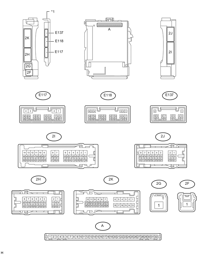
Text in Illustration *1 Main Body ECU (Multiplex Network Body ECU) - -
-
Disconnect the E118, 2K and 2J ECU connectors.
-
Measure the voltage and resistance according to the value(s) in the table below.
Terminal No. (Symbol) Wiring Color Terminal Description Condition Specified Condition A-31 (BECU) - Body ground - Battery power supply Always 11 to 14 V A-30 (ACC) - Body ground - ACC power supply Ignition switch off Below 1 V Ignition switch ON 11 to 14 V A-32 (IG) - Body ground - Ignition power supply Ignition switch off Below 1 V Ignition switch ON 11 to 14 V A-11 (GND1) - Body ground - Ground Always Below 1 Ω 2G-1 (TRLY) - Body ground W - Body ground Taillight power supply Always 11 to 14 V E118-6 (FLCY) - Body ground V - Body ground Front door courtesy light switch LH signal Front door LH open Below 1 Ω V - Body ground Front door courtesy light switch LH signal Front door LH closed 10 kΩ or higher E118-27 (FRCY) - Body ground V - Body ground Front door courtesy light switch RH signal Front door RH open Below 1 Ω V - Body ground Front door courtesy light switch RH signal Front door RH closed 10 kΩ or higher 2K-34 (LCTY) - Body ground BE - Body ground Rear door courtesy light switch LH signal Rear door LH open Below 1 Ω BE - Body ground Rear door courtesy light switch LH signal Rear door LH closed 10 kΩ or higher 2J-29 (RCTY) - Body ground BE - Body ground Rear door courtesy light switch RH signal Rear door RH open Below 1 Ω BE - Body ground Rear door courtesy light switch RH signal Rear door RH closed 10 kΩ or higher 2K-31 (BCTY) - Body ground W - Body ground Back door courtesy light switch signal Back door open Below 1 Ω W - Body ground Back door courtesy light switch signal Back door closed 10 kΩ or higher E118-22 (TAIL) - Body ground B - Body ground Light control switch TAIL signal Light control switch tail Below 1 Ω B - Body ground Light control switch TAIL signal Light control switch except tail 10 kΩ or higher E118-12 (HEAD) - Body ground R- Body ground Light control switch HEAD signal Light control switch head Below 1 Ω R - Body ground Light control switch HEAD signal Light control switch except head 10 kΩ or higher E118-8 (A) - Body ground P - Body ground Light control switch AUTO signal Light control switch AUTO Below 1 Ω P - Body ground Light control switch AUTO signal Light control switch except AUTO 10 kΩ or higher E118-26 (FFOG) - Body ground*1 W - Body ground Front fog light switch signal Front fog light switch on Below 1 Ω W - Body ground Front fog light switch signal Front fog light switch off 10 kΩ or higher E118-23 (RFOG) - Body ground*2 P - Body ground Rear fog light switch signal Rear fog light switch on Below 1 Ω P - Body ground Rear fog light switch signal Rear fog light switch off 10 kΩ or higher E118-24 (HU) - Body ground V - Body ground Dimmer switch high signal Dimmer switch high Below 1 Ω V - Body ground Dimmer switch high signal Dimmer switch except high or flash 10 kΩ or higher E118-10 (HF) - Body ground L - Body ground Dimmer switch flash signal Dimmer switch flash Below 1 Ω L - Body ground Dimmer switch flash Signal Dimmer switch except flash 10 kΩ or higher 2J-30 (ILE) - Body ground G - Body ground*3
SB - Body ground*4
Interior light signal Map light on Below 1 Ω G - Body ground*3
SB - Body ground*4
Interior light signal Map light off 10 kΩ or higher 2J-11 (DOMR) - Body ground*4 R - Body ground Battery save system (interior light auto cut function) signal Battery save system (interior light auto cut function) operating 11 to 14 V R - Body ground Battery save system (interior light auto cut function) signal Battery save system (interior light auto cut function) not operating Below 1 V
-
*1: w/ Front Fog Light
-
*2: w/ Rear Fog Light
-
*3: w/o Door Ajar Warning Buzzer Function
-
*4: w/ Door Ajar Warning Buzzer Function
-
-
Reconnect the E118, 2K and 2J ECU connectors.
-
Measure the voltage according to the value(s) in the table below.
Terminal No. (Symbol) Wiring Color Terminal Description Condition Specified Condition 2H-31 (FFGO) - Body ground*1 L - Body ground Front fog light signal Light control switch tail,
front fog light switch on
Below 1 V L - Body ground Front fog light signal Light control switch tail,
front fog light switch off
11 to 14 V 2H-30 (HRLY) - Body ground B - Body ground Headlight low beam signal Light control switch head,
dimmer switch low
Below 1 V B - Body ground Headlight low beam signal Light control switch head,
dimmer switch except low
11 to 14 V 2H-28 (DRLE) - Body ground*2 R - Body ground Daytime running light signal Daytime running light on Below 1 V R - Body ground Daytime running light signal Daytime running light off 11 to 14 V E118-1 (DIM) - Body ground B - Body ground Headlight High beam signal Light control switch head,
dimmer switch high
Below 1 V B - Body ground Headlight High beam signal Light control switch head,
dimmer switch except high
11 to 14 V E117-23 (AHBI) - Body ground*3 L - Body ground Auto high beam switch signal input Automatic high beam switch on Below 1 V Automatic high beam switch off 11 to 14 V E118-20 (CLTS) - Body ground R - Body ground Automatic light control sensor signal input Ignition switch off Below 1 V Ignition switch ON, headlight dimmer switch in AUTO position, material which blocks light used to cover and then uncover top of automatic light control sensor Pulse generation
(See waveform 1)
-
*1: w/ Front Fog Light
-
*2: w/ w/ Daytime Running Light
-
*3: w/ Automatic High Beam System
-
-
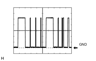
Waveform 1
Item Content Terminal No. (Symbol) E118-20 (CLTS) - Body ground Tool Setting 2 V/DIV., 10 ms./DIV. Condition Ignition switch ON, headlight dimmer switch in AUTO position, material which blocks light used to cover and then uncover top of automatic light control sensor
-
-
CHECK COMBINATION METER ASSEMBLY
-
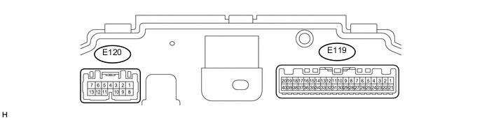
Disconnect the E119 and E120 combination meter connectors.
-
Measure the voltage and resistance according to the value(s) in the table below.
Terminal No. (Symbol) Wiring Color Terminal Description Condition Specified Condition E119-21 (B) - Body ground V - Body ground IG power supply Ignition switch off Below 1 V Ignition switch ON 11 to 14 V E119-22 (IG+) - Body ground BE - Body ground Ground Ignition switch off → Ignition switch ON Below 1 V → 8.5 to 14 V E120-1 (B) - Body ground P - Body ground Battery Ignition switch off 11 to 14 V E120-11 (HZSW) - Body ground P - Body ground Hazard warning signal switch signal (Output) Ignition switch ON, hazard warning signal switch on 11 to 14 V Ignition switch ON, hazard warning signal switch off Below 1 V E119-20 (ET) - Body ground BR - Body ground Ground Always Below 1 Ω -
Reconnect the E119 and E120 combination meter connectors.
-
Measure the voltage according to the value(s) in the table below.
Terminal No. (Symbol) Wiring Color Terminal Description Condition Specified Condition E120-9 (ER) - Body ground B - Body ground RH turn indicator light signal (Input) Ignition switch ON, RH turn signal switch on Below 1 V Ignition switch ON, RH turn signal switch off 11 to 14 V E120-10 (EL) - Body ground L - Body ground LH turn indicator light signal (Input) Ignition switch ON, LH turn signal switch on Below 1 V Ignition switch ON, LH turn signal switch off 11 to 14 V E120-7 (LL) - Body ground L - Body ground LH turn indicator light signal (Output) Ignition switch ON, LH turn indicator light off Below 1 V Ignition switch ON, LH turn indicator light blinking 11 to 14 V ←→ Below 1 V E120-13 (LR) - Body ground R - Body ground RH turn indicator light signal (Output) Ignition switch ON, RH turn indicator light off Below 1 V Ignition switch ON, LH turn indicator light blinking 11 to 14 V ←→ Below 1 V
-
-
CHECK HEADLIGHT LEVELING ECU ASSEMBLY (w/ Static Headlight Auto Leveling)

-
Disconnect the E109 headlight leveling ECU connector.
-
Measure the voltage and resistance according to the value(s) in the table below.
Terminal No. (Symbol) Wiring Color Terminal Description Condition Specified Condition E109-1 (IG) - Body ground G - Body ground Ignition power supply Ignition switch off Below 1 V Ignition switch ON 11 to 14 V E109-9 (E1) - Body ground W-B - Body ground Ground Always Below 1 Ω If the result is not as specified, there may be a malfunction on the wire harness side.
-
Reconnect the E109 headlight leveling ECU connector.
-
Measure the voltage and resistance according to the value(s) in the table below.
Terminal No. (Symbol) Wiring Color Terminal Description Condition Specified Condition E109-10 (RH+) - E109-9 (E1) L - W-B Headlight leveling motor RH power supply Ignition switch off Below 1 V Ignition switch ON 11 to 14 V E109-11 (LH+) - E109-9 (E1) L - W-B Headlight leveling motor LH power supply Ignition switch off Below 1 V Ignition switch ON 11 to 14 V E109-12 (SBR) - E109-21 (SGR) B - G Rear height control sensor power supply Ignition switch off Below 1 V Ignition switch ON 4.75 to 5.25 V E109-17 (RHT) - E109-9 (E1) P - W-B Headlight leveling motor RH operation signal input With low beam headlights on, vehicle height not changed Below 1 V With low beam headlights on, vehicle height changed and maintained for more than 3 seconds 1.0 to 14.4 V E109-18 (LHT) - E109-9 (E1) P - W-B Headlight leveling motor LH operation signal input With low beam headlights on, vehicle height not changed Below 1 V With low beam headlights on, vehicle height changed and maintained for more than 3 seconds 1.0 to 14.4 V E109-19 (SHRL) - E109- 21 (SGR) R - G Rear height control sensor signal input Ignition switch off Below 1 V Ignition switch ON 0.5 to 4.5 V E109-21 (SGR) - E109-9 (E1) G - W-B Rear height control sensor ground Always Below 1 Ω E109-23 (RH-) - E109-9 (E1) R - W-B Headlight leveling motor RH ground Always Below 1 Ω E109-24 (LH-) - E109-9 (E1) R - W-B Headlight leveling motor LH ground Always Below 1 Ω
-
-
CHECK HEADLIGHT SWIVEL ECU ASSEMBLY (w/ Dynamic Headlight Auto Leveling)

-
Disconnect the E101 headlight swivel ECU connector.
-
Measure the voltage and resistance according to the value(s) in the table below.
Terminal No. (Symbol) Wiring Color Terminal Description Condition Specified Condition E101-14 (IGS) - Body ground R - Body ground Ignition power supply Ignition switch off Below 1 V Ignition switch ON 11 to 14 V E101-15 (IG) - Body ground G - Body ground Ignition power supply Ignition switch off Below 1 V Ignition switch ON 11 to 14 V E101-22 (E1) - Body ground W-B - Body ground Ground Always Below 1 Ω If the result is not as specified, there may be a malfunction on the wire harness side.
-
Reconnect the E101 headlight swivel ECU connector.
-
Measure the voltage and resistance according to the value(s) in the table below.
Terminal No. (Symbol) Wiring Color Terminal Description Condition Specified Condition E101-2 (SMBR) - E101-22 (E1) L - W-B Headlight leveling motor RH power supply Ignition switch off Below 1 V Ignition switch ON 11 to 14 V E101-11 (SMBL) - E101-22 (E1) L - W-B Headlight leveling motor LH power supply Ignition switch off Below 1 V Ignition switch ON 11 to 14 V E101-18 (SBR) - E101-21 (SGR) B - G Rear height control sensor power supply Ignition switch off Below 1 V Ignition switch ON 4.75 to 5.25 V E101-11 (RH+) - E101-22 (E1) P - W-B Headlight leveling motor RH operation signal input With low beam headlights on, vehicle height not changed Below 1 V With low beam headlights on, vehicle height changed and maintained for more than 3 seconds 1.0 to 14.4 V E101-30 (LH+) - E101-21 (E1) P - W-B Headlight leveling motor LH operation signal input With low beam headlights on, vehicle height not changed Below 1 V With low beam headlights on, vehicle height changed and maintained for more than 3 seconds 1.0 to 14.4 V E101-19 (SHRL) - E101- 21 (SGR) R - G Rear height control sensor signal input Ignition switch off Below 1 V Ignition switch ON 0.5 to 4.5 V E101-21 (SGR) - E101-21 (E1) G - W-B Rear height control sensor ground Always Below 1 Ω E101-26 (RH-) - E101-21 (E1) R - W-B Headlight leveling motor RH ground Always Below 1 Ω E101-27 (LH-) - E101-21 (E1) R - W-B Headlight leveling motor LH ground Always Below 1 Ω
-
-
CHECK NO. 2 MAIN BODY ECU (w/ Side Step Light)
-
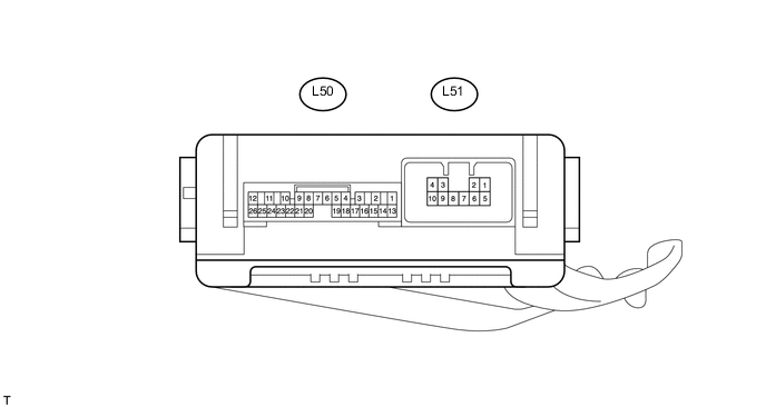
Disconnect the L50 and L51 ECU connectors.
-
Measure the voltage and resistance according to the value(s) in the table below.
Terminal No. (Symbol) Wiring Color Terminal Description Condition Specified Condition L50-14 (BECU) - Body ground R - Body ground Battery power supply Always 11 to 14 V L50-13 (SIG) - Body ground B - Body ground Ignition power supply Ignition switch off Below 1 V Ignition switch ON 11 to 14 V L50-7 (GND) - Body ground W-B - Body ground Ground Always Below 1 Ω L51-7 (GND) - Body ground W-B - Body ground Ground Always Below 1 Ω
-
If the result is not as specified, there may be a malfunction on the wire harness side.
-
-
Reconnect the L50 and L51 ECU connectors.
-
Measure the voltage according to the value(s) in the table below.
Terminal No. (Symbol) Wiring Color Terminal Description Condition Specified Condition L50-9 (RBD1) - Body ground L - Body ground Step light LH signal Step light LH on Below 1 V Step light LH off 11 to 14 V L50-21 (RBD2) - Body ground L - Body ground Step light RH signal Step light RH on Below 1 V Step light RH off 11 to 14 V
-
-
CHECK INNER REAR VIEW MIRROR ASSEMBLY (w/o Pre-crash Safety System)

-
Disconnect the R16 mirror connector.
-
Measure the voltage and resistance according to the value(s) in the table below.
Terminal No. (Symbol) Wiring Color Terminal Description Condition Specified Condition R16-1 (IG) - Body ground B - Body ground IG power supply Ignition switch ON 11 to 14 V R16-2 (E) - Body ground W-B - Body ground Ground Always Below 1 Ω R16-9 (CANH) - Body ground G - Body ground CAN communication line Ignition switch ON Pulse generation R16-10 (CANL) - Body ground B - Body ground CAN communication line Ignition switch ON Pulse generation
-
-
FORWARD RECOGNITION CAMERA (w/ Pre-crash Safety System)