LIGHTING SYSTEM Rear Fog Light Circuit
DESCRIPTION
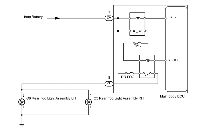
The main body ECU receives a rear fog light switch information signal from the light control switch (rear fog switch), and illuminates the rear fog lights.
WIRING DIAGRAM
PROCEDURE
-
PERFORM ACTIVE TEST USING INTELLIGENT TESTER
-
Operate the intelligent tester according to the steps on the display and select "Active Test".
Main Body Tester Display Test Part Control Range Diagnostic Note Rear Fog Light Relay Rear fog light ON or OFF - OK Fog light turns on/turns off.
OK 
PROCEED TO NEXT CIRCUIT INSPECTION SHOWN IN PROBLEM SYMPTOMS TABLE Click here
NG 
-
-
INSPECT FUSE (RR FOG, TAIL)
-
Remove the RR FOG fuse and TAIL fuse from the main body ECU.
-
Measure the resistance according to the value(s) in the table below.
Standard Resistance Tester Connection Condition Specified Condition RR FOG fuse Always Below 1 Ω TAIL fuse
NG
REPLACE FUSE
OK
-
-
CHECK HARNESS AND CONNECTOR (MAIN BODY ECU - BODY GROUND)
-
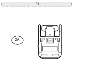
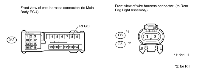
*1 Front view of wire harness connector: (to Main Body ECU) Disconnect the 2A ECU connector.
-
Measure the voltage according to the value(s) in the table below.
Standard Voltage Tester Connection Condition Specified Condition 2A-1 - Body ground Always 11 to 14 V
NG
REPAIR OR REPLACE HARNESS OR CONNECTOR
OK
-
-
CHECK HARNESS AND CONNECTOR (REAR FOG LIGHT ASSEMBLY - MAIN BODY ECU AND BODY GROUND)
-
Disconnect the 2C ECU connector.
-
for LH:
-
Disconnect the O6 rear fog light connector.
-
Measure the resistance according to the value(s) in the table below.
Standard Resistance Tester Connection Condition Specified Condition 2C-8 (RFGO) - O6-2 Always Below 1 Ω O6-1 - Body ground O6-2 - Body ground Always 10 kΩ or higher
-
-
for RH:
-
Disconnect the O5 rear fog light connector.
-
Measure the resistance according to the value(s) in the table below.
Standard Resistance Tester Connection Condition Specified Condition 2C-8 (RFGO) - O5-2 Always Below 1 Ω O5-1 - Body ground O5-2 - Body ground Always 10 kΩ or higher
-
OK
REPLACE MAIN BODY ECU
NG
REPAIR OR REPLACE HARNESS OR CONNECTOR
-