LIGHTING SYSTEM Headlight (HI-BEAM) Circuit
DESCRIPTION
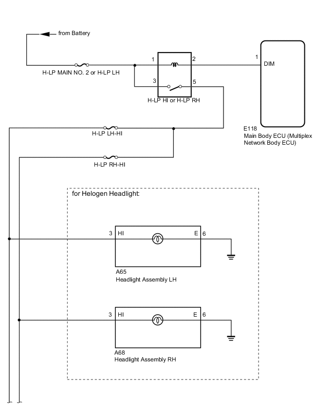
The main body ECU receives a headlight hi switch information signal from the light control switch, and illuminates the headlight high beam.
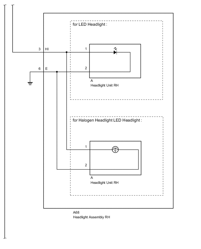
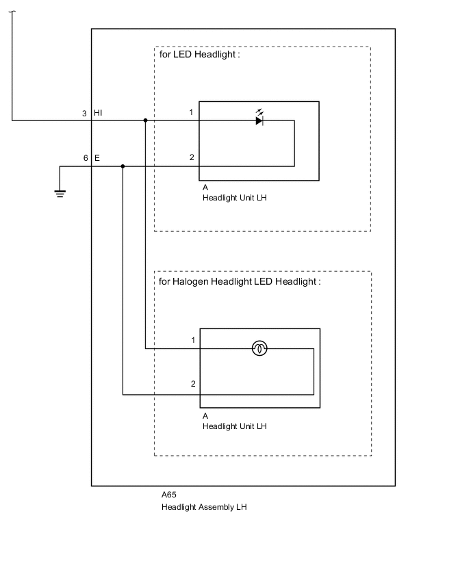
WIRING DIAGRAM
CAUTION / NOTICE / HINT
Note
Inspect the fuses and bulbs for circuits related to this system before performing the following inspection procedure.
PROCEDURE
-
READ VALUE USING GTS (HEAD LIGHT SW [HEAD])
-
Operate the GTS according to the display and select the Data List Click here.
Main Body Tester Display Measurement Item/Range Normal Condition Diagnostic Note Head Light SW (Head) Headlight switch signal / ON or OFF ON: Headlight switch (Head) on
OFF: Headlight switch (Head) off
- OK Normal conditions listed above are displayed.
OK 
PROCEED TO NEXT CIRCUIT INSPECTION SHOWN IN PROBLEM SYMPTOMS TABLE Click here
NG 
-
-
PERFORM ACTIVE TEST USING GTS (HEAD HI RELAY)
-
Using the GTS, perform the Active Test Click here.
Main Body Tester Display Test Part Control Range Diagnostic Note Head Light Hi Headlight (Hi) ON or OFF - OK Headlight high beam turns on/turns off. Result Result Proceed to Headlights (Both high beams turn on) (for LHD) A Headlights (Both high beams turn on) (for RHD) B Headlights (Neither high beam turns on) C Headlight on one side (High beam does not turn on) D Headlight on one side (High beam does not turn on) [for Halogen Headlight] E
A
REPLACE MAIN BODY ECU (MULTIPLEX NETWORK BODY ECU) Click here
B
REPLACE MAIN BODY ECU (MULTIPLEX NETWORK BODY ECU) Click here
D 
CHECK HARNESS AND CONNECTOR (HEADLIGHT RELAY [H-LP HI OR H-LP RH] - HEADLIGHT ASSEMBLY Click here
E
REPLACE HEADLIGHT ASSEMBLY Click here
C
-
-
INSPECT HEADLIGHT RELAY (H-LP HI OR H-LP RH)
-
Remove the H-LP HI or H-LP RH relay from the engine room relay block, junction block.
-
Inspect the H-LP HI or H-LP RH relay Click here.
NG
REPLACE HEADLIGHT RELAY (H-LP HI OR H-LP RH)
OK
-
-
CHECK HARNESS AND CONNECTOR (BATTERY - HEADLIGHT RELAY [H-LP HI OR H-LP RH])
-
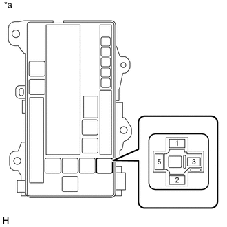
Text in Illustration *a Front view of wire harness connector
(to Headlight Relay [H-LP HI or H-LP RH])
Remove the H-LP HI or H-LP RH relay from the engine room relay block, junction block.
-
Measure the voltage according to the value(s) in the table below.
Standard Voltage Tester Connection Condition Specified Condition Headlight relay terminal 1- Body ground Always 11 to 14 V Headlight relay terminal 3 - Body ground
NG
REPAIR OR REPLACE HARNESS OR CONNECTOR
OK
-
-
CHECK HARNESS AND CONNECTOR (HEADLIGHT RELAY [H-LP HI OR H-LP RH] - HEADLIGHT ASSEMBLY
-
Remove the H-LP HI or H-LP RH relay from the engine room relay block, junction block.
-
Disconnect the A65*1 or A68*2 headlight connector.
-
*1: for LH
-
*2: for RH
-
-
Measure the resistance according to the value(s) in the table below.
Standard Resistance for LH Tester Connection Condition Specified Condition Headlight relay terminal 5 - A65-3 (HI) Always Below 1 Ω Headlight relay terminal 5 - Body ground Always 10 kΩ or higher for RH Tester Connection Condition Specified Condition Headlight relay terminal 5 - A68-3 (HI) Always Below 1 Ω Headlight relay terminal 5 - Body ground Always 10 kΩ or higher
NG
REPAIR OR REPLACE HARNESS OR CONNECTOR
OK
-
-
CHECK HARNESS AND CONNECTOR (MAIN BODY ECU [MULTIPLEXNETWORK BODY ECU] - HEADLIGHT RELAY [H-LP HI OR H-LP RH]
-
Remove the H-LP HI or H-LP RH relay from the engine room relay block, junction block.
-
Remove the cowl side junction block LH.
-
Disconnect the E118 main body ECU connector.
-
Measure the resistance according to the value(s) in the table below.
Standard Resistance Tester Connection Condition Specified Condition Headlight relay terminal 2 - E118-1 (DIM) Always Below 1 Ω E118-1 (DIM) - Body ground Always 10 kΩ or higher Result Result Proceed to OK (for LHD) A OK (for RHD) B NG C
A
REPLACE MAIN BODY ECU (MULTIPLEX NETWORK BODY ECU) Click here
B
REPLACE MAIN BODY ECU (MULTIPLEX NETWORK BODY ECU) Click here
C
REPAIR OR REPLACE HARNESS OR CONNECTOR
-
-
CHECK HARNESS AND CONNECTOR (HEADLIGHT RELAY [H-LP HI OR H-LP RH] - HEADLIGHT ASSEMBLY
-
Remove the H-LP HI or H-LP RH relay from the engine room relay block, junction block.
-
Disconnect the A65*1 or A68*2 headlight connector.
-
*1: for LH
-
*2: for RH
-
-
Measure the resistance according to the value(s) in the table below.
Standard Resistance for LH Tester Connection Condition Specified Condition Headlight relay terminal 5 - A65-3 (HI) Always Below 1 Ω A65-6 (E) - Body ground Always Headlight relay terminal 5 - Body ground Always 10 kΩ or higher for RH Tester Connection Condition Specified Condition Headlight relay terminal 5 - A68-3 (HI) Always Below 1 Ω A68-6 (E) - Body ground Always Headlight relay terminal 5 - Body ground Always 10 kΩ or higher
NG
REPAIR OR REPLACE HARNESS OR CONNECTOR
OK
-
-
INSPECT HEADLIGHT ASSEMBLY
-
for LED Headlight
-
Remove the headlight assembly Click here.
-
-
for Halogen Headlight and LED Headlight
-
Remove the headlight assembly Click here.
-
-
for LED Headlight
-
Remove the headlight unit from the headlight assembly Click here.
-
-
for Halogen Headlight and LED Headlight
-
Remove the headlight unit from the headlight assembly Click here.
-
-
Measure the resistance according to the value(s) in the table below.
Standard Resistance for LED Headlight Tester Connection Condition Specified Condition A-3 (B) - B-1 Always Below 1 Ω A-6 (E) - B-2 Always 10 kΩ or higher for Halogen Headlight and LED Headlight Tester Connection Condition Specified Condition A-3 (B) - B-1 Always Below 1 Ω A-6 (E) - B-2 Always 10 kΩ or higher Result Result Proceed to OK (for LED Headlight) A OK (for Halogen Headlight and LED Headlight) B NG (for LED Headlight) C NG (for Halogen Headlight and LED Headlight) D
A
REPLACE HEADLIGHT UNIT Click here
B
REPLACE HEADLIGHT UNIT Click here
C
REPLACE HEADLIGHT ASSEMBLY Click here
D
REPLACE HEADLIGHT ASSEMBLY Click here
-