LIGHTING SYSTEM Headlight Dimmer Switch Circuit
DESCRIPTION
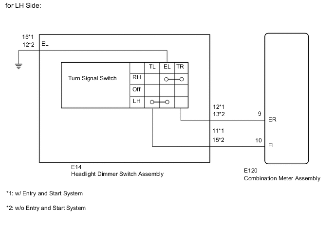
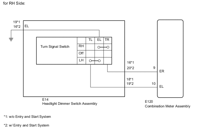
The combination meter assembly receives the turn signal switch information and controls the turn signal lights.
WIRING DIAGRAM
CAUTION / NOTICE / HINT
Note
When replacing the combination meter assembly, make sure to replace it with a new one.
PROCEDURE
-
READ VALUE USING GTS (TURN SIGNAL SWITCH)
-
Operate the GTS according to the display and select the Data List Click here.
Combination Meter Tester Display Measurement Item/Range Normal Condition Diagnostic Note Turn Signal Switch (Right) Turn signal switch (right) / ON or OFF ON: Turn signal switch (right) on
OFF: Turn signal switch (right) off
- Turn Signal Switch (Left) Turn signal switch (left) / ON or OFF ON: Turn signal switch (left) on
OFF: Turn signal switch (left) off
- Result: Result Proceed to Data List values are as specified A Data List values are not as specified B
A 
PROCEED TO NEXT SUSPECTED AREA SHOWN IN PROBLEM SYMPTOMS TABLE Click here
B 
-
-
INSPECT HEADLIGHT DIMMER SWITCH ASSEMBLY
-
Remove the headlight dimmer switch Click here.
-
Inspect the headlight dimmer switch Click here.
NG
REPLACE HEADLIGHT DIMMER SWITCH Click here
OK
-
-
CHECK HARNESS AND CONNECTOR (HEADLIGHT DIMMER SWITCH - COMBINATION METER AND BODY GROUND)
-
Disconnect the E14 switch connector.
-
Disconnect the E120 meter connector.
-
Measure the resistance according to the value(s) in the table below.
Standard Resistance for LH Side (w/o Entry and Start System) Tester Connection Condition Specified Condition E14-15 (TL) - E120-10 (EL) Always Below 1 Ω E14-13 (TR) - E120-9 (ER) E14-12 (ET) - Body ground E14-15 (TL) - Body ground Always 10 kΩ or higher E14-13 (TR) - Body ground for LH Side (w/ Entry and Start System) Tester Connection Condition Specified Condition E14-11 (TL) - E120-10 (EL) Always Below 1 Ω E14-12 (TR) - E120-9 (ER) E14-15 (ET) - Body ground E14-11 (TL) - Body ground Always 10 kΩ or higher E14-12 (TR) - Body ground for RH Side (w/o Entry and Start System) Tester Connection Condition Specified Condition E14-18 (TL) - E120-10 (EL) Always Below 1 Ω E14-16 (TR) - E120-9 (ER) E14-19 (ET) - Body ground E14-18 (TL) - Body ground Always 10 kΩ or higher E14-16 (TR) - Body ground for RH Side (w/ Entry and Start System) Tester Connection Condition Specified Condition E14-19 (TL) - E120-10 (EL) Always Below 1 Ω E14-20 (TR) - E120-9 (ER) E14-16 (ET) - Body ground E14-19 (TL) - Body ground Always 10 kΩ or higher E14-20 (TR) - Body ground
OK
REPLACE COMBINATION METER ASSEMBLY Click here
NG
REPAIR OR REPLACE HARNESS OR CONNECTOR
-