WIPER AND WASHER SYSTEM(w/o Rain Sensor) TERMINALS OF ECU
-
CHECK HEADLIGHT CLEANER CONTROL RELAY (w/ Headlight Cleaner System)

Tech Tips
The headlight cleaner control relay uses waterproof connector. Therefore, voltage cannot be checked with the connector connected to the vehicle.
Terminal No. (Symbol) Wiring Color Terminal Description Condition Specified Condition 3 (IG) - 4 (E) - IG signal circuit Ignition switch off Below 1 V Ignition switch ON 11 to 14 V 4 (E) - Body ground - Ground circuit Always Below 1 Ω 6 (PB) - 4 (E) - Headlight cleaner motor operation signal Headlight cleaner motor is stopped 11 to 14 V Headlight cleaner motor is operating Below 1 V 2 (H) - 4 (E) - Headlight cleaner switch and headlight switch operation signal Ignition switch ON
Headlight cleaner switch is off
Below 1 V Ignition switch ON
Headlight switch is off
Below 1 V Ignition switch ON
Headlight cleaner switch is on and headlight dimmer switch in HEAD
11 to 14 V 5 (FRWA) - 4 (E)* - Front washer switch operation signal Ignition switch ON
Front washer switch is off
11 to 14 V Ignition switch ON
Front washer switch is on
Below 1 V 1 (HDLO) - 4 (E)* - Headlight low beam operation signal Ignition switch ON
Headlight dimmer switch in HEAD
11 to 14 V Ignition switch ON
Headlight dimmer switch not in HEAD
Below 1 V
-
*: w/ Headlight Auto Leveling
-
-
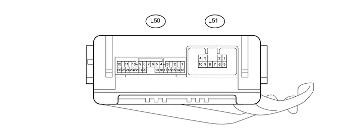
NO. 2 MULTIPLEX NETWORK BODY ECU (w/ Washer Nozzle Heater System)
-
Disconnect the L50 and L51 No. 2 multiplex network body ECU connectors.
-
Measure the voltage and resistance according to the value(s) in the table below.
Terminal No. (Symbol) Wiring Color Terminal Description Condition Specified Condition L50-14 (BECU) - Body ground R - Body ground Power source circuit Always 11 to 14 V L50-13 (SIG) - Body ground G - Body ground IG signal circuit Ignition switch ON 11 to 14 V Ignition switch off Below 1 V L50-7 (GND) - Body ground W-B - Body ground Ground circuit Always Below 1 Ω -
Reconnect the L50 and L51 No. 2 multiplex network body ECU connectors.
-
Measure the voltage according to the value(s) in the table below.
Terminal No. (Symbol) Wiring Color Terminal Description Condition Specified Condition L50-25 (WHTR) - Body ground GR - Body ground Washer nozzle heater signal circuit Ignition switch ON, ambient temperature 6°C (42°F) or higher 11 to 14 V Ignition switch ON, ambient temperature 5°C (41°F) or less Below 1 V
-