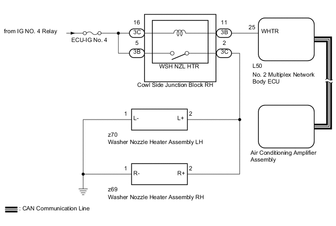
WIPER AND WASHER SYSTEM(w/ Rain Sensor) Washer Nozzle Heater Circuit
DESCRIPTION
The No. 2 multiplex network body ECU receives ambient air temperature information from the air conditioning amplifier assembly via CAN communication.
The washer nozzle heater assembly controls the No. 2 multiplex network body ECU and operates the washer nozzle heater assembly according to the ambient temperature.
WIRING DIAGRAM
CAUTION / NOTICE / HINT
Note
-
Inspect the fuses for circuits related to this system before performing the following inspection procedure.
-
Since the wiper and washer system has functions that use CAN communication, first confirm that there is no malfunction in the CAN communication system with the How to Proceed with Troubleshooting procedure Click here.
-
Since the wiper and washer system has functions that use the air conditioning system, first confirm that there is no malfunction in the air conditioning system with the How to Proceed with Troubleshooting procedure Click here.
PROCEDURE
-
CHECK NO. 2 MULTIPLEX NETWORK BODY ECU
-
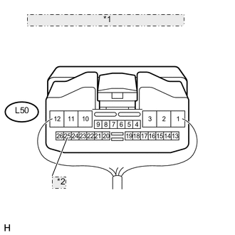
*1 Component with harness connected: (No. 2 Multiplex Network Body ECU) *2 WHTR Using the intelligent tester, enter the following menus: Body / Body No. 4 / Active Test.
-
Select "Front Washer Nozzle Heater", and perform the Active Test.
-
Measure the voltage according to the value(s) in the table below.
Standard Voltage Tester Connection Condition Specified Condition L50-25 (WHTR) - Body ground
-
Engine switch on (IG)
-
Active Test is not performed
11 to 14 V L50-25 (WHTR) - Body ground
-
Engine switch on (IG)
-
Active Test is performed
Below 1 V -
NG 
CHECK HARNESS AND CONNECTOR (NO. 2 MULTIPLEX NETWORK BODY ECU - COWL SIDE JUNCTION BLOCK RH) Click here
OK 
-
-
INSPECT WASHER NOZZLE HEATER ASSEMBLY
-
for LH:
-
Remove the washer nozzle heater assembly LH Click here.
-
Inspect the washer nozzle heater assembly LH Click here.
-
-
for RH:
-
Remove the washer nozzle heater assembly RH Click here.
-
Inspect the washer nozzle heater assembly RH Click here.
Result Result Proceed to OK A NG (for LH) B NG (for RH) C -
B 
REPLACE WASHER NOZZLE HEATER ASSEMBLY LH Click here
C
REPLACE WASHER NOZZLE HEATER ASSEMBLY RH Click here
A
-
-
CHECK HARNESS AND CONNECTOR (WASHER NOZZLE HEATER ASSEMBLY - COWL SIDE JUNCTION BLOCK RH AND BODY GROUND)
-
Disconnect the z70 washer nozzle heater assembly LH connector.
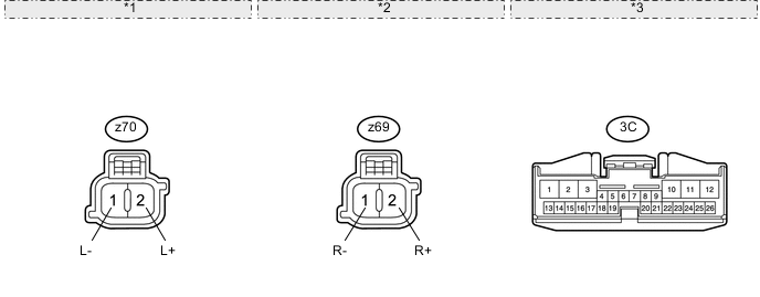
*1 Front view of wire harness connector: (to Washer Nozzle Heater Assembly LH) *2 Front view of wire harness connector: (to Washer Nozzle Heater Assembly RH) *3 Front view of wire harness connector: (to Cowl Side Junction Block RH) -
Disconnect the z69 washer nozzle heater assembly RH connector.
-
Disconnect the 3C cowl side junction block RH connector.
-
Measure the resistance according to the value(s) in the table below.
Standard Resistance Tester Connection Condition Specified Condition z70-2 (L+) - 3C-2 Always Below 1 Ω z69-2 (R+) - 3C-2 Always Below 1 Ω z70-1 (L-) - Body ground Always Below 1 Ω z69-1 (R-) - Body ground Always Below 1 Ω z70-2 (L+) or 3C-2 - Body ground Always 10 kΩ or higher z69-2 (R+) or 3C-2 - Body ground Always 10 kΩ or higher
NG
REPAIR OR REPLACE HARNESS OR CONNECTOR
OK
-
-
CHECK HARNESS AND CONNECTOR (COWL SIDE JUNCTION BLOCK RH - BATTERY)
-
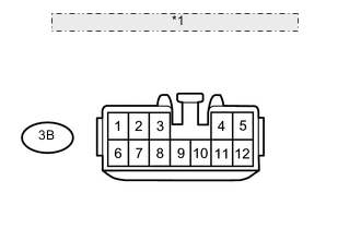
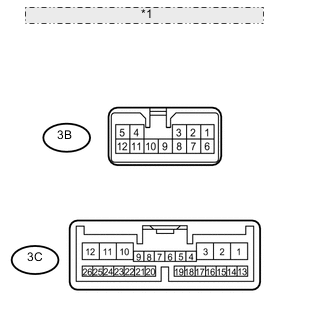
*1 Front view of wire harness connector: (to Cowl Side Junction Block RH) Disconnect the 3B cowl side junction block RH connector.
-
Measure the voltage according to the value(s) in the table below.
Standard Voltage Tester Connection Switch Condition Specified Condition 3B-5 - Body ground Engine switch on (IG) 11 to 14 V 3B-5 - Body ground Engine switch off Below 1 V
NG
REPAIR OR REPLACE HARNESS OR CONNECTOR
OK
-
-
CHECK COWL SIDE JUNCTION BLOCK RH
-
*1 Component without harness connected: (Cowl Side Junction Block RH) Remove the cowl side junction block RH.
-
Measure the resistance according to the value(s) in the table below.
Standard Resistance Tester Connection Condition Specified Condition 3B-5 - 3C-2 Battery voltage applied between terminals 3C-16 and 3B-11 Below 1 Ω 3B-5 - 3C-2 Battery voltage not applied between terminals 3C-16 and 3B-11 10 kΩ or higher Result Result Proceed to OK (w/ Sliding Roof System) A OK (w/o Sliding Roof System) B NG C
A
REPLACE NO. 2 MULTIPLEX NETWORK BODY ECU Click here
B
REPLACE NO. 2 MULTIPLEX NETWORK BODY ECU Click here
C
REPAIR OR REPLACE HARNESS OR CONNECTOR
-
-
CHECK HARNESS AND CONNECTOR (NO. 2 MULTIPLEX NETWORK BODY ECU - COWL SIDE JUNCTION BLOCK RH)
-
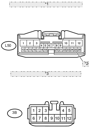
*1 Front view of wire harness connector: (to No. 2 Multiplex Network Body ECU) *2 WHTR *3 Front view of wire harness connector: (to Cowl Side Junction Block RH) Disconnect the L50 No. 2 multiplex network body ECU connector.
-
Disconnect the 3B cowl side junction block RH connector.
-
Measure the resistance according to the value(s) in the table below.
Standard Resistance Tester Connection Condition Specified Condition L50-25 (WHTR) - 3B-11 Always Below 1 Ω L50-25 (WHTR) or 3B-11 - Body ground Always 10 kΩ or higher
NG
REPAIR OR REPLACE HARNESS OR CONNECTOR
OK
-
-
CHECK HARNESS AND CONNECTOR (COWL SIDE JUNCTION BLOCK RH - BATTERY)
-
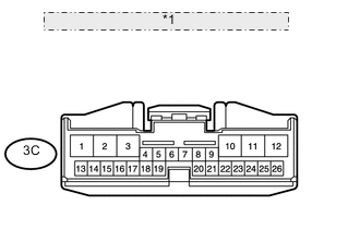
*1 Front view of wire harness connector: (to Cowl Side Junction Block RH) Disconnect the 3C cowl side junction block RH connector.
-
Measure the voltage according to the value(s) in the table below.
Standard Voltage Tester Connection Switch Condition Specified Condition 3C-16 - Body ground Engine switch on (IG) 11 to 14 V 3C-16 - Body ground Engine switch off Below 1 V
NG
REPAIR OR REPLACE HARNESS OR CONNECTOR
OK
-
-
INSPECT COWL SIDE JUNCTION BLOCK RH
-
*1 Component without harness connected: (Cowl Side Junction Block RH) Remove the cowl side junction block RH.
-
Measure the resistance according to the value(s) in the table below.
Standard Resistance Tester Connection Condition Specified Condition 3B-5 - 3C-2 Battery voltage applied between terminals 3C-16 and 3B-11 Below 1 Ω 3B-5 - 3C-2 Battery voltage not applied between terminals 3C-16 and 3B-11 10 kΩ or higher Result Result Proceed to OK (w/ Sliding Roof System) A OK (w/o Sliding Roof System) B NG C
A
REPLACE NO. 2 MULTIPLEX NETWORK BODY ECU Click here
B
REPLACE NO. 2 MULTIPLEX NETWORK BODY ECU Click here
C
REPLACE COWL SIDE JUNCTION BLOCK RH
-