WIPER AND WASHER SYSTEM(w/ Rain Sensor) TERMINALS OF ECU
-
CHECK WINDSHIELD WIPER RELAY
-
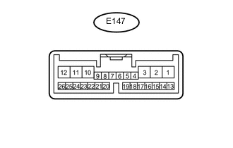
Disconnect the E147 windshield wiper relay connectors.
-
Measure the voltage and resistance according to the value(s) in the table below.
Terminal No. (Symbol) Wiring Color Terminal Description Condition Specified Condition E147-2 (IG) - Body ground B - Body ground IG power supply Engine switch on (IG) 11 to 14 V Engine switch off Below 1 V E147-8 (VR2) - E147-21 (VR1) W -R Adjust volume circit Windshield wiper switch adjusting ring changed 0 to 231 Ω E147-12 (E) - Body ground W-B - Body ground Body ground Always Below 1 Ω E147-16 (WIG) - Body ground B - Body ground IG power supply Engine switch on (IG) 11 to 14 V Engine switch off Below 1 V -
Reconnect the E147 windshield wiper relay connectors.
-
Measure the voltage according to the value(s) in the table below.
Terminal No. (Symbol) Wiring Color Terminal Description Condition Specified Condition E147-1 (+SM) - Body ground W - Body ground Front wiper motor operation signal Front wiper is operated 11 to 14 V Front wiper is stopped Below 1 V E147-3 (C1) - E147-5 (CO) L - R Windshield wiper assembly AUTO position signal Windshield wiper assembly in AUTO position Below 1 V Windshield wiper assembly in not AUTO position 11 to 14 V E147-10 (+1) - Body ground W - Body ground Front wiper motor low speed signal Front wiper motor in low operation 11 to 14 V Front wiper motor not operation 11 to 14 V E147-11 (+2) - Body ground R - Body ground Front wiper motor high speed signal Front wiper motor in high operation Below 1 V Front wiper motor not operation Below 1 V E147-14 (MPX1) - Body ground B - Body ground LIN communication signal Engine switch on (IG) Below 1 V E147-25 (W) - Body ground L - Body ground Front washer motor signal Front washer switch off 11 to 14 V Front washer switch on Below 1 V
-
-
CHECK WINDSHIELD WIPER SWITCH
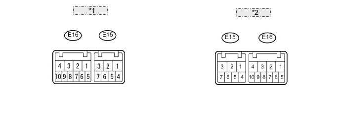
*1 for RH side: *2 for LH side:
-
Disconnect the E16 switch connector.
-
Measure the voltage and resistance according to the value(s) in the table below.
Terminal No. (Symbol) Wiring Color Terminal Description Condition Specified Condition E16-2 (+B) - E16-10 (E)*1 B - W-B Power source circuit (from battery) Engine switch off Below 1 V Engine switch on (IG) 11 to 14 V E16-3 (+B) - E16-5 (E)*2 B - W-B Power source circuit (from battery) Engine switch off Below 1 V Engine switch on (IG) 11 to 14 V E16-10 (E) - Body ground*1 W-B - Body ground Ground circuit Always Below 1 Ω E16-5 (E) - Body ground*2 W-B - Body ground Ground circuit Always Below 1 Ω Tech Tips
-
*1: for LH Side
-
*2: for RH Side
-
-
-
CHECK RAIN SENSOR

-
Disconnect the R11 rain sensor connector.
-
Measure the voltage and resistance according to the value(s) in the table below.
Terminal No. (Symbol) Wiring Color Terminal Description Condition Specified Condition R11-4 (SIG) - Body ground G - Body ground IG signal circuit Engine switch off Below 1 V Engine switch on (IG) 11 to 14 V R11-1 (ES) - Body ground W - Body ground Ground circuit Always Below 1 Ω -
Reconnect the R11 rain sensor connector.
-
Measure the waveform according to the value(s) in the table below.
Terminal No. (Symbol) Wiring Color Terminal Description Condition Specified Condition R11-3 (MPX) - Body ground R - Body ground LIN communication signal Engine switch on (IG) Pulse generation
-
-
NO. 2 MULTIPLEX NETWORK BODY ECU (w/ Washer Nozzle Heater System)
-
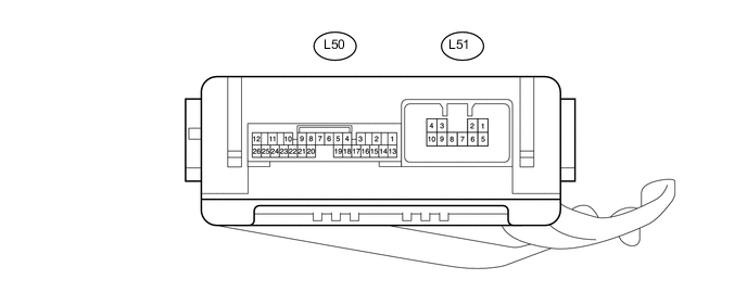
Disconnect the L50 and L51 No. 2 multiplex network body ECU connectors.
-
Measure the voltage and resistance according to the value(s) in the table below.
Terminal No. (Symbol) Wiring Color Terminal Description Condition Specified Condition L50-14 (BECU) - Body ground R - Body ground Power source circuit Always 11 to 14 V L50-13 (SIG) - Body ground G - Body ground IG signal circuit Engine switch off Below 1 V Engine switch on (IG) 11 to 14 V L50-7 (GND) - Body ground W-B - Body ground Ground circuit Always Below 1 Ω -
Reconnect the L50 and L51 No. 2 multiplex network body ECU connectors.
-
Measure the voltage according to the value(s) in the table below.
Terminal No. (Symbol) Wiring Color Terminal Description Condition Specified Condition L50-25 (WHTR) - Body ground GR - Body ground Washer nozzle heater signal circuit Engine switch on (IG), ambient temperature 6°C (42°F) or higher 11 to 14 V Engine switch on (IG), ambient temperature 5°C (41°F) or less Below 1 V
-