Click here
-
CHECK WINDSHIELD WIPER ECU
-
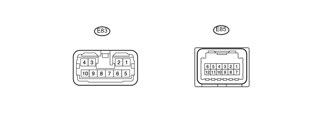
Disconnect the E83 and E85 ECU connectors.
-
Measure the voltage and resistance according to the value(s) in the table below.
Terminal No. (Symbol) Wiring Color Terminal Description Condition Specified Condition E83-5 (IG1I) - E85-10 (E) G - W-B IG signal circuit Engine switch off Below 1 V Engine switch on (IG) 11 to 14 V E85-10 (E) - Body ground W-B - Body ground Ground circuit Always Below 1 Ω If the result is not as specified, there may be a malfunction on the wire harness side.
-
Reconnect the E83 and E85 ECU connectors.
-
Measure the voltage and waveform according to the value(s) in the table below.
Terminal No. (Symbol) Wiring Color Terminal Description Condition Specified Condition E83-7 (+SM) - Body ground W - Body ground Front wiper motor operation signal Front wiper is operated 11 to 14 V Front wiper is stopped Below 1 V E83-8 (WIG) - Body ground B - Body ground Front wiper motor power source circuit Engine switch off Below 1 V Engine switch on (IG) 11 to 14 V E83-10 (1S) - Body ground P - Body ground Front wiper motor power supply circuit Front wiper switch off Below 1 V Front wiper switch LO 11 to 14 V E83-9 (2S) - Body ground R - Body ground Front wiper motor power supply circuit (HI signal) Front wiper switch off Below 1 V Front wiper switch HI 11 to 14 V E85-2 (W) - Body ground L - Body ground Front washer motor power source circuit Front washer switch off Below 1 V Front washer switch on 11 to 14 V E85-5 (CANL) - Body ground R - Body ground CAN communication signal Engine switch on (IG) Pulse generation E85-6 (CANH) - Body ground LG - Body ground CAN communication signal Engine switch on (IG) Pulse generation E85-7 (MPX1) - Body ground R - Body ground LIN communication signal Engine switch on (IG) Pulse generation
-
-
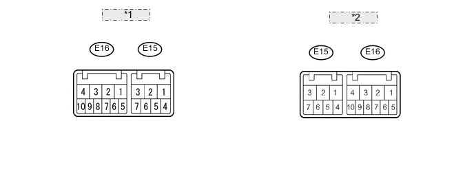
Table 1. *1 for RH side: *2 for LH side: CHECK WINDSHIELD WIPER SWITCH
-
Disconnect the E16 switch connector.
-
Measure the voltage and resistance according to the value(s) in the table below.
Terminal No. (Symbol) Wiring Color Terminal Description Condition Specified Condition E16-2 (+B) - E16-10 (E)*1 B - W-B Power source circuit (from battery) Engine switch off Below 1 V Engine switch on (IG) 11 to 14 V E16-3 (+B) - E16-5 (E)*2 B - W-B Power source circuit (from battery) Engine switch off Below 1 V Engine switch on (IG) 11 to 14 V E16-10 (E) - Body ground*1 W-B - Body ground Ground circuit Always Below 1 Ω E16-5 (E) - Body ground*2 W-B - Body ground Ground circuit Always Below 1 Ω Tip:
-
*1: for LH Side
-
*2: for RH Side
-
-
-
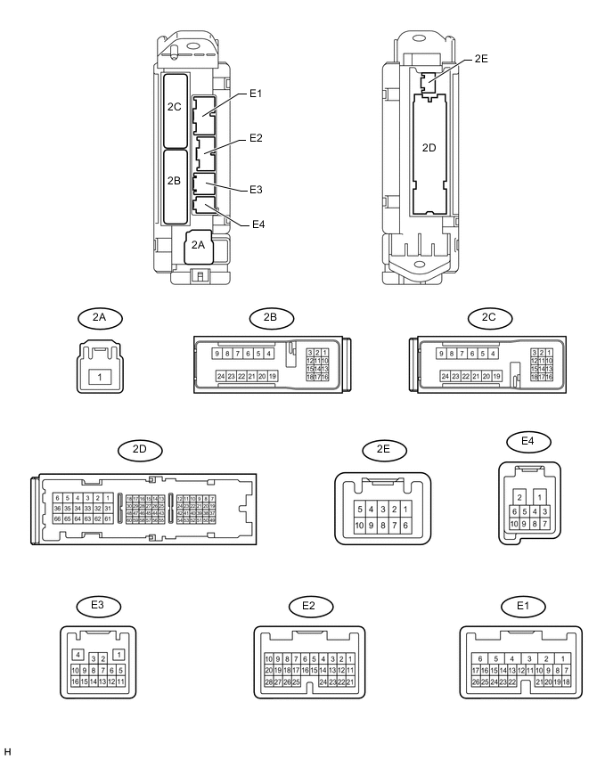
CHECK MAIN BODY ECU (COWL SIDE JUNCTION BLOCK LH)
-
Disconnect the 2D, E2 and E1 main body ECU connectors.
-
Measure the voltage and resistance according to the value(s) in the table below.
Terminal No. (Symbol) Wiring Color Terminal Description Condition Specified Condition E1-6 (AM1) - 2D-62 (GND2) W - W-B Power source circuit (from battery) Always 11 to 14 V E2-11 (IG2D) - 2D-62 (GND2) B - W-B IG signal circuit Engine switch off Below 1 V Engine switch on (IG) 11 to 14 V 2B-22 (STP) - 2D-62 (GND2) R - W-B Stop light switch circuit Stop light switch off Below 1 V Stop light switch on 11 to 14 V 2D-62 (GND2) - Body ground W-B - Body ground Ground circuit Always Below 1 Ω -
Reconnect the 2D, E2 and E1 main body ECU connectors.
-
Measure the voltage and waveform according to the value(s) in the table below.
Terminal No. (Symbol) Wiring Color Terminal Description Condition Specified Condition E2-13 (HDLO) - Body ground L - Body ground Headlight low beam operation signal Engine switch on (IG)
Headlight dimmer switch in head
11 to 14 V Engine switch on (IG)
Headlight dimmer switch not in head
Below 1 V E3-15 (CANN) - Body ground R - Body ground CAN communication signal Engine switch on (IG) Pulse generation E3-16 (CANP) - Body ground GR - Body ground CAN communication signal Engine switch on (IG) Pulse generation
-
-
CHECK MAP LIGHT
-
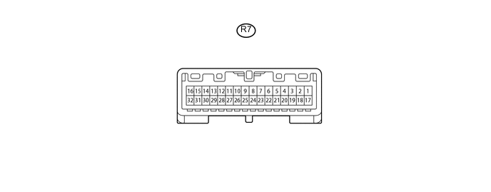
Disconnect the R7 map light connector.
-
Measure the voltage and resistance according to the value(s) in the table below.
Terminal No. (Symbol) Wiring Color Terminal Description Condition Specified Condition R7-14 (IG) - R7-3 (GND5) G - W-B IG signal circuit Engine switch off Below 1 V Engine switch on (IG) 11 to 14 V R7-3 (GND5) - Body ground W-B - Body ground Ground circuit Always Below 1 Ω
-
-

CHECK RAIN SENSOR
-
Disconnect the R11 rain sensor connector.
-
Measure the voltage and resistance according to the value(s) in the table below.
Terminal No. (Symbol) Wiring Color Terminal Description Condition Specified Condition R11-4 (SIG) - Body ground G - Body ground IG signal circuit Engine switch off Below 1 V Engine switch on (IG) 11 to 14 V R11-1 (ES) - Body ground W - Body ground Ground circuit Always Below 1 Ω -
Reconnect the R11 rain sensor connector.
-
Measure the waveform according to the value(s) in the table below.
Terminal No. (Symbol) Wiring Color Terminal Description Condition Specified Condition R11-3 (MPX) - Body ground R - Body ground LIN communication signal Engine switch on (IG) Pulse generation
-
-

CHECK HEADLIGHT CLEANER CONTROL RELAY (w/ Headlight Cleaner System)
Tip:The headlight cleaner control relay uses waterproof connector. Therefore, voltage cannot be checked with the connector connected to the vehicle.
Terminal No. (Symbol) Wiring Color Terminal Description Condition Specified Condition 3 (IG) - 4 (E) - IG signal circuit Engine switch off Below 1 V Engine switch on (IG) 11 to 14 V 4 (E) - Body ground - Ground circuit Always Below 1 Ω 6 (PB) - 4 (E) - Headlight cleaner motor operation signal Headlight cleaner motor is stopped 11 to 14 V Headlight cleaner motor is operating Below 1 V 2 (H) - 4 (E) - Headlight cleaner switch and headlight switch operation signal Engine switch on (IG)
Headlight cleaner switch is off
Below 1 V Engine switch on (IG)
Headlight switch is off
Below 1 V Engine switch on (IG)
Headlight cleaner switch is on and headlight dimmer switch in HEAD
11 to 14 V 5 (FRWA) - 4 (E)* - Front washer switch operation signal Engine switch on (IG)
Front washer switch is off
11 to 14 V Engine switch on (IG)
Front washer switch is on
Below 1 V 1 (HDLO) - 4 (E)* - Headlight low beam operation signal Engine switch on (IG)
Headlight dimmer switch in HEAD
11 to 14 V Engine switch on (IG)
Headlight dimmer switch not in HEAD
Below 1 V
-
*: w/ Headlight Auto Leveling
-
-
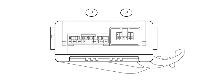
NO. 2 MULTIPLEX NETWORK BODY ECU (w/ Washer Nozzle Heater System)
-
Disconnect the L50 and L51 No. 2 multiplex network body ECU connectors.
-
Measure the voltage and resistance according to the value(s) in the table below.
Terminal No. (Symbol) Wiring Color Terminal Description Condition Specified Condition L50-14 (BECU) - Body ground R - Body ground Power source circuit Always 11 to 14 V L50-13 (SIG) - Body ground G - Body ground IG signal circuit Engine switch off Below 1 V Engine switch on (IG) 11 to 14 V L50-7 (GND) - Body ground W-B - Body ground Ground circuit Always Below 1 Ω -
Reconnect the L50 and L51 No. 2 multiplex network body ECU connectors.
-
Measure the voltage according to the value(s) in the table below.
Terminal No. (Symbol) Wiring Color Terminal Description Condition Specified Condition L50-25 (WHTR) - Body ground GR - Body ground Washer nozzle heater signal circuit Engine switch on (IG), ambient temperature 6°C (42°F) or higher 11 to 14 V Engine switch on (IG), ambient temperature 5°C (41°F) or less Below 1 V
-