OUTER REAR VIEW MIRROR INSPECTION
PROCEDURE
-
INSPECT OUTER REAR VIEW MIRROR ASSEMBLY LH (w/o Retract Mirror)
-
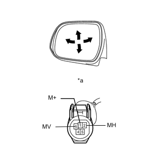
Text in Illustration *a Component without harness connected
(Outer Rear View Mirror Assembly LH)
Apply battery voltage and check the operation of the mirror.
OK Measurement Condition Specified Condition Battery positive (+) → Terminal 3 (MV)
Battery negative (-) → Terminal 1 (M+)
Turns upward (A) Battery positive (+) → Terminal 1 (M+)
Battery negative (-) → Terminal 3 (MV)
Turns downward (B) Battery positive (+) → Terminal 2 (MH)
Battery negative (-) → Terminal 1 (M+)
Turns left (C) Battery positive (+) → Terminal 1 (M+)
Battery negative (-) → Terminal 2 (MH)
Turns right (D) If the result is not as specified, replace the outer rear view mirror assembly LH.
-
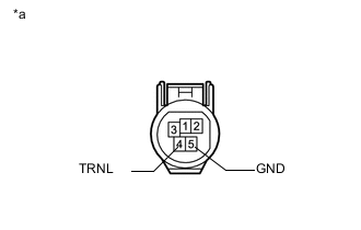
Text in Illustration *a Component without harness connected
(Outer Rear View Mirror Assembly LH)
w/ Side Turn Signal Light:
-
Check the side turn light assembly.
-
Apply battery voltage to the terminals of the connector, and check the illumination condition.
OK Measurement Connection Specified Condition Battery positive (+) → Terminal 4 (TRNL)
Negative (-) end of the battery → Terminal 5 (GND)
Side turn light illuminates If the result is not as specified, check the side turn signal light assembly LH Click here.
-
-
-
INSPECT OUTER REAR VIEW MIRROR ASSEMBLY RH (w/o Retract Mirror)
-
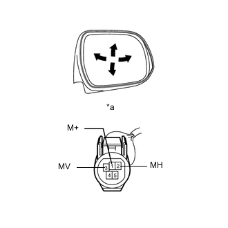
Text in Illustration *a Component without harness connected
(Outer Rear View Mirror Assembly RH)
Apply battery voltage and check the operation of the mirror.
OK Measurement Condition Specified Condition Battery positive (+) → Terminal 3 (MV)
Battery negative (-) → Terminal 1 (M+)
Turns upward (A) Battery positive (+) → Terminal 1 (M+)
Battery negative (-) → Terminal 3 (MV)
Turns downward (B) Battery positive (+) → Terminal 2 (MH)
Battery negative (-) → Terminal 1 (M+)
Turns right (C) Battery positive (+) → Terminal 1 (M+)
Battery negative (-) → Terminal 2 (MH)
Turns left (D) If the result is not as specified, replace the outer rear view mirror assembly RH.
-
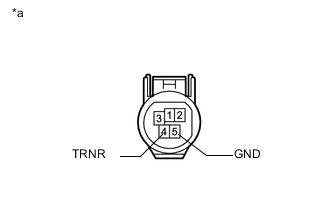
Text in Illustration *a Component without harness connected
(Outer Rear View Mirror Assembly RH)
/ Side Turn Signal Light:
-
Check the side turn light assembly.
-
Apply battery voltage to the terminals of the connector, and check the illumination condition.
OK Measurement Connection Specified Condition Battery positive (+) → Terminal 4 (TRNR)
Negative (-) end of the battery → Terminal 5 (GND)
Side turn light illuminates If the result is not as specified, check the side turn signal light assembly RH Click here.
-
-
-
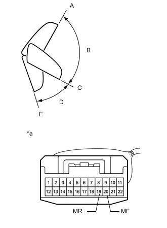
INSPECT OUTER REAR VIEW MIRROR ASSEMBLY LH (w/ Retract Mirror)
-
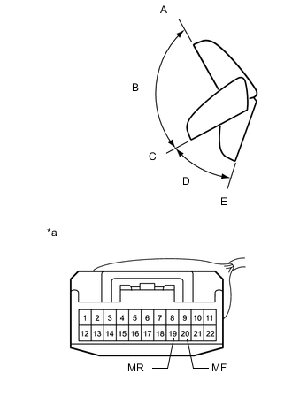
Text in Illustration *a Component without harness connected
(Outer Rear View Mirror Assembly LH)
For each position: Disconnect the battery, set the mirror position by hand, connect the battery, and check the retractable mirror movement.
OK Measurement Condition Mirror Position Specified Condition Battery positive (+) → Terminal 19 (MR)
Battery negative (-) → Terminal 20 (MF)
Forward position A Moves from A to retracted position E Battery negative (-) → Terminal 19 (MR)
Battery positive (+) → Terminal 20 (MF)
Forward position A Does not move Battery positive (+) → Terminal 19 (MR)
Battery negative (-) → Terminal 20 (MF)
Position between forward position A and driving position C Moves from B to retracted position E Battery negative (-) → Terminal 19 (MR)
Battery positive (+) → Terminal 20 (MF)
Position between forward position A and driving position C Moves from B to forward position A Battery positive (+) → Terminal 19 (MR)
Battery negative (-) → Terminal 20 (MF)
Driving position C Moves from C to retracted position E Battery negative (-) → Terminal 19 (MR)
Battery positive (+) → Terminal 20 (MF)
Driving position C Does not move Battery positive (+) → Terminal 19 (MR)
Battery negative (-) → Terminal 20 (MF)
Position between driving position C and retracted position E Moves from D to retracted position E Battery negative (-) → Terminal 19 (MR)
Battery positive (+) → Terminal 20 (MF)
Position between driving position C and retracted position E Moves from D to driving position C Battery positive (+) → Terminal 19 (MR)
Battery negative (-) → Terminal 20 (MF)
Retracted position E Does not move Battery negative (-) → Terminal 19 (MR)
Battery positive (+) → Terminal 20 (MF)
Retracted position E Moves from E to driving position C Note
-
Disconnect and reconnect the battery between each mirror position check.
-
Do not apply battery voltage when moving the mirror by hand into each mirror position.
If the result is not as specified, replace the outer rear view mirror assembly LH.
-
-
Text in Illustration *a Component without harness connected
(Outer Rear View Mirror Assembly LH)
Apply battery voltage and check the operation of the mirror.
OK Measurement Condition Specified Condition Battery positive (+) → Terminal 7 (MV)
Battery negative (-) → Terminal 8 (M+)
Turns upward Battery negative (-) → Terminal 8 (M+)
Battery positive (+) → Terminal 7 (MV)
Turns downward Battery positive (+) → Terminal 9 (MH)
Battery negative (-) → Terminal 8 (M+)
Turns left Battery negative (-) → Terminal 8 (M+)
Battery positive (+) → Terminal 9 (MH)
Turns right If the result is not as specified, replace the outer rear view mirror assembly LH.
-
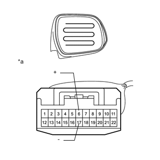
Text in Illustration *a Component without harness connected
(Outer Rear View Mirror Assembly LH)
w/ Mirror Heater:
-
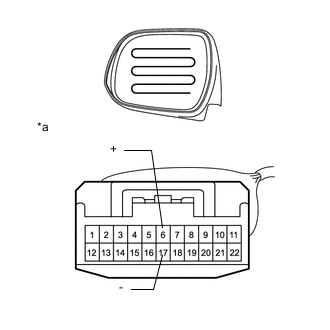
Check the mirror heater.
-
Measure the resistance according to the value (s) in the table below.
Standard Resistance Tester Connection Condition Specified Condition Terminal 6 (+) - Terminal 17 (-) 25°C (75°F) 3.0 to 3.9 Ω If the result is not as specified, replace the outer rear view mirror assembly LH.
-
Apply battery voltage and check the operation of the mirror heater.
OK Measurement Condition Specified Condition Battery positive (+) → Terminal 6 (+)
Battery negative (-) → Terminal 17 (-)
Mirror becomes warm Tech Tips
It will take a short time for the mirror to become warm.
If the result is not as specified, replace the outer rear view mirror assembly LH.
-
-
Text in Illustration *a Component without harness connected
(Outer Rear View Mirror Assembly LH)
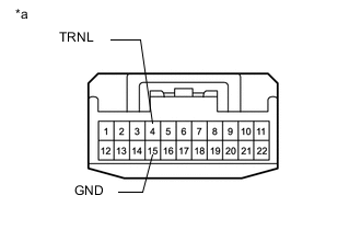
Check the side turn light assembly.
-
Apply battery voltage to the terminals of the connector, and check the illumination condition.
OK Measurement Connection Specified Condition Battery positive (+) → Terminal 4 (TRNL)
Negative (-) end of the battery → Terminal 15 (GND)
Side turn light illuminates If the result is not as specified, check the side turn signal light assembly LH Click here.
-
-
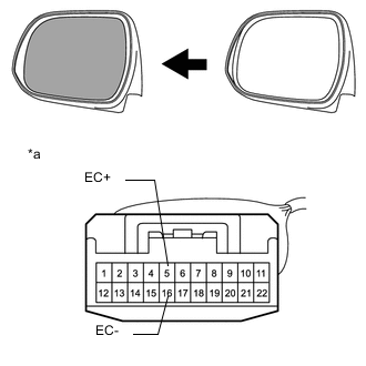
Text in Illustration *a Component without harness connected
(Outer Rear View Mirror Assembly LH)
w/EC Mirror:
-
Check the EC mirror operation.
-
Connect 1.5 V dry-cell battery.
-
Apply dry battery voltage and check operation of the mirror face, as shown in the table and illustration.
OK Measurement Condition Specified Condition Battery positive (+) → Terminal 5 (EC+)
Battery negative (-) → Terminal 16 (EC-)
Mirror surface becomes dark If the result is not as specified, replace the outer rear view mirror assembly LH.
-
-
-
INSPECT OUTER REAR VIEW MIRROR ASSEMBLY RH (w/ Retract Mirror)
-
Text in Illustration *a Component without harness connected
(Outer Rear View Mirror Assembly RH)
For each position: Disconnect the battery, set the mirror position by hand, connect the battery, and check the retractable mirror movement.
OK Measurement Condition Mirror Position Specified Condition Battery positive (+) → Terminal 19 (MR)
Battery negative (-) → Terminal 20 (MF)
Forward position A Moves from A to retracted position E Battery negative (-) → Terminal 19 (MR)
Battery positive (+) → Terminal 20 (MF)
Forward position A Does not move Battery positive (+) → Terminal 19 (MR)
Battery negative (-) → Terminal 20 (MF)
Position between forward position A and driving position C Moves from B to retracted position E Battery negative (-) → Terminal 19 (MR)
Battery positive (+) → Terminal 20 (MF)
Position between forward position A and driving position C Moves from B to forward position A Battery positive (+) → Terminal 19 (MR)
Battery negative (-) → Terminal 20 (MF)
Driving position C Moves from C to retracted position E Battery negative (-) → Terminal 19 (MR)
Battery positive (+) → Terminal 20 (MF)
Driving position C Does not move Battery positive (+) → Terminal 19 (MR)
Battery negative (-) → Terminal 20 (MF)
Position between driving position C and retracted position E Moves from D to retracted position E Battery negative (-) → Terminal 19 (MR)
Battery positive (+) → Terminal 20 (MF)
Position between driving position C and retracted position E Moves from D to driving position C Battery positive (+) → Terminal 19 (MR)
Battery negative (-) → Terminal 20 (MF)
Retracted position E Does not move Battery negative (-) → Terminal 19 (MR)
Battery positive (+) → Terminal 20 (MF)
Retracted position E Moves from E to driving position C Note
-
Disconnect and reconnect the battery between each mirror position check.
-
Do not apply battery voltage when moving the mirror by hand into each mirror position.
If the result is not as specified, replace the outer rear view mirror assembly RH.
-
-
Text in Illustration *a Component without harness connected
(Outer Rear View Mirror Assembly RH)
Apply battery voltage and check the operation of the mirror.
OK Measurement Condition Specified Condition Battery positive (+) → Terminal 7 (MV)
Battery negative (-) → Terminal 8 (M+)
Turns upward Battery negative (-) → Terminal 8 (M+)
Battery positive (+) → Terminal 7 (MV)
Turns downward Battery positive (+) → Terminal 9 (MH)
Battery negative (-) → Terminal 8 (M+)
Turns left Battery negative (-) → Terminal 8 (M+)
Battery positive (+) → Terminal 9 (MH)
Turns right If the result is not as specified, replace the outer rear view mirror assembly RH.
-
Text in Illustration *a Component without harness connected
(Outer Rear View Mirror Assembly RH)
w/ Mirror Heater:
-
Check the mirror heater.
-
Measure the resistance according to the value (s) in the table below.
Standard Resistance Tester Connection Condition Specified Condition Terminal 6 (+) - Terminal 17 (-) 25°C (75°F) 3.0 to 3.9 Ω If the result is not as specified, replace the outer rear view mirror assembly RH.
-
Apply battery voltage and check the operation of the mirror heater.
OK Measurement Condition Specified Condition Battery positive (+) → Terminal 6 (+)
Battery negative (-) → Terminal 17 (-)
Mirror becomes warm Tech Tips
It will take a short time for the mirror to become warm.
If the result is not as specified, replace the outer rear view mirror assembly.
-
-
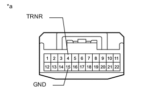
Text in Illustration *a Component without harness connected
(Outer Rear View Mirror Assembly RH)
Check the side turn light assembly.
-
Apply battery voltage to the terminals of the connector, and check the illumination condition.
OK Measurement Connection Specified Condition Battery positive (+) → Terminal 4 (TRNR)
Negative (-) end of the battery → Terminal 15 (GND)
Side turn light illuminates If the result is not as specified, check the side turn signal light assembly RH Click here.
-
-
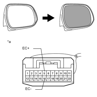
Text in Illustration *a Component without harness connected
(Outer Rear View Mirror Assembly RH)
w/EC Mirror:
-
Check the EC mirror operation.
-
Connect 1.5 V dry-cell battery.
-
Apply dry battery voltage and check operation of the mirror face, as shown in the table and illustration.
OK Measurement Condition Specified Condition Battery positive (+) → Terminal 5 (EC+)
Battery negative (-) → Terminal 16 (EC-)
Mirror surface becomes dark If the result is not as specified, replace the outer rear view mirror assembly RH.
-
-