POWER MIRROR CONTROL SYSTEM(w/ Retract Mirror) Power Retractable Mirrors do not Operate with Power Retract Mirror Switch
SYSTEM DESCRIPTION
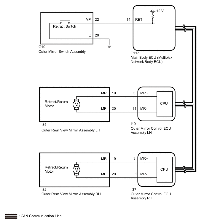
When the outer mirror switch assembly is pushed, the main body ECU (multiplex network body ECU) received retract/return signal from the outer mirror switch assembly. Then main body ECU (multiplex network body ECU) sends the retract/return signal to outer mirror control ECU LH and RH via the CAN communication line. The outer mirror control ECU assembly then performs control in response to the retract/return signal.
WIRING DIAGRAM
PROCEDURE
-
READ VALUE USING GTS (MIRROR RETRACT SWITCH)
-
Using the GTS, read the Data List. Click here.
Main Body Tester Display Measurement Item/Range Normal Condition Diagnostic Note Outer Mirror Fold SW Mirror retract switch signal / ON or OFF ON: Switch on (retracting)
OFF: Switch off
- OK On the GTS screen, each item changes between ON and OFF according to above chart.
NG 
INSPECT OUTER MIRROR SWITCH ASSEMBLY Click here
OK 
-
-
CONFIRM MALFUNCTIONING PARTS
-
Check the malfunctioning outer rear view mirror assembly Click here.
Result Result Proceed to Both outer rear view mirror assembly LH and RH do not operate (for LHD) A Both outer rear view mirror assembly LH and RH do not operate (for RHD) B Outer rear view mirror assembly LH does not operate C Outer rear view mirror assembly RH does not operate D
A 
REPLACE MAIN BODY ECU (MULTIPLEX NETWORK BODY ECU) Click here
B
REPLACE MAIN BODY ECU (MULTIPLEX NETWORK BODY ECU) Click here
D
INSPECT OUTER REAR VIEW MIRROR ASSEMBLY RH Click here
C
-
-
INSPECT OUTER REAR VIEW MIRROR ASSEMBLY LH
-
Remove the outer rear view mirror assembly LH Click here.
-
Inspect the outer rear view mirror assembly LH Click here.
NG
REPLACE OUTER REAR VIEW MIRROR ASSEMBLY LH Click here
OK
-
-
CHECK HARNESS AND CONNECTOR (OUTER REAR VIEW MIRROR ASSEMBLY LH - OUTER MIRROR CONTROL ECU ASSEMBLY LH)
-
Disconnect the I35 outer rear view mirror assembly LH connector.
-
Disconnect the I40 outer mirror control ECU assembly LH connector.
-
Measure the resistance according to the value(s) in the table below.
Standard Resistance Tester Connection Condition Specified Condition I35-19 (MR) - I40-3 (MR+) Always Below 1 Ω I35-20 (MF) - I40-11 (MR-) I35-19 (MR) or I40-3 (MR+) - Body ground Always 10 kΩ or higher I35-20 (MF) or I40-11 (MR-) - Body ground
OK
REPLACE OUTER MIRROR CONTROL ECU ASSEMBLY LH Click here
NG
REPAIR OR REPLACE HARNESS OR CONNECTOR
-
-
INSPECT OUTER REAR VIEW MIRROR ASSEMBLY RH
-
Remove the outer rear view mirror assembly RH Click here.
-
Inspect the outer rear view mirror assembly RH Click here.
NG
REPLACE OUTER REAR VIEW MIRROR ASSEMBLY RH Click here
OK
-
-
CHECK HARNESS AND CONNECTOR (OUTER REAR VIEW MIRROR ASSEMBLY RH - OUTER MIRROR CONTROL ECU ASSEMBLY RH)
-
Disconnect the I32 outer rear view mirror assembly RH connector.
-
Disconnect the I37 outer mirror control ECU assembly RH connector.
-
Measure the resistance according to the value(s) in the table below.
Standard Resistance Tester Connection Condition Specified Condition I32-19 (MR) - I37-3 (MR+) Always Below 1 Ω I32-20 (MF) - I37-11 (MR-) I32-19 (MR) or I37-3 (MR+) - Body ground Always 10 kΩ or higher I32-20 (MF) or I37-11 (MR-) - Body ground
OK
REPLACE OUTER MIRROR CONTROL ECU ASSEMBLY RH Click here
NG
REPAIR OR REPLACE HARNESS OR CONNECTOR
-
-
INSPECT OUTER MIRROR SWITCH ASSEMBLY
-
Remove the outer mirror switch assembly Click here.
-
Inspect the outer mirror switch assembly Click here.
NG
REPLACE OUTER MIRROR SWITCH ASSEMBLY Click here
OK
-
-
CHECK HARNESS AND CONNECTOR (OUTER MIRROR SWITCH ASSEMBLY - MAIN BODY ECU [MULTIPLEX NETWORK BODY ECU] AND BODY GROUND)
-
Disconnect the G19 outer mirror switch assembly connector.
-
Disconnect the E117 main body ECU (multiplex network body ECU ) connector.
-
Measure the resistance according to the value(s) in the table below.
Standard Resistance Tester Connection Condition Specified Condition G19-22 (MF) - E117-14 (RET) Always Below 1 Ω G19-20 (E) - Body ground G19-22 (MF) or E117-14 (RET) - Body ground Always 10 kΩ or higher Result Result Proceed to OK (for LHD) A OK (for RHD) B NG C
A
REPLACE MAIN BODY ECU (MULTIPLEX NETWORK BODY ECU) Click here
B
REPLACE MAIN BODY ECU (MULTIPLEX NETWORK BODY ECU) Click here
C
REPAIR OR REPLACE HARNESS OR CONNECTOR
-