POWER MIRROR CONTROL SYSTEM(w/ Retract Mirror) Power Mirror cannot be Adjusted with Power Mirror Switch
DESCRIPTION
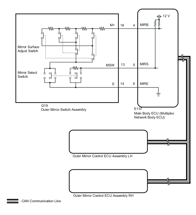
When the outer mirror switch assembly mirror select switch is operated, right/left selection signals are sent to the main body ECU (multiplex network body ECU). The main body ECU (multiplex network body ECU) sends the received right/left selection signals to the outer mirror control ECU assemblies via CAN communication.
WIRING DIAGRAM
CAUTION / NOTICE / HINT
Note
-
First perform the communication function inspections in How to Proceed with Troubleshooting to confirm that there are no CAN communication malfunctions before troubleshooting this problem Click here.
-
If the main body ECU (multiplex network body ECU) is replaced, refer to the Entry and Start System Click here.
PROCEDURE
-
READ VALUE USING GTS (POWER MIRROR SWITCH)
-
Using the GTS, read the Data List. Click here.
Main Body Tester Display Measurement Item/Range Normal Condition Diagnostic Note Mirror Selection SW (R) Mirror select switch signal for RH mirror / ON or OFF ON: Mirror select switch is R position
OFF: Mirror select switch is except R position
- Mirror Selection SW (L) Mirror select switch signal for LH mirror / ON or OFF ON: Mirror select switch is L position
OFF: Mirror select switch is except L position
- Mirror Position SW (R) Mirror surface adjust switch signal (Right) / ON or OFF ON: Mirror surface adjust switch pressed right
OFF: Mirror surface adjust switch not pressed right
- Mirror Position SW (L) Mirror surface adjust switch signal (Left) / ON or OFF ON: Mirror surface adjust switch not pressed left
OFF: Mirror surface adjust switch pressed left
- Mirror Position SW (Up) Mirror surface adjust switch signal (Up) / ON or OFF ON: Mirror surface adjust switch pressed up
OFF: Mirror surface adjust switch not pressed up
- Mirror Position SW (Dwn) Mirror surface adjust switch signal (Down) / ON or OFF ON: Mirror surface adjust switch pressed down
OFF: Mirror surface adjust switch not pressed down
- OK On the GTS screen, each item changes between ON and OFF according to above chart. Result Proceed to OK A NG (for LHD) B NG (for RHD) C
B 
REPLACE MAIN BODY ECU (MULTIPLEX NETWORK BODY ECU) Click here
C
REPLACE MAIN BODY ECU (MULTIPLEX NETWORK BODY ECU) Click here
A 
-
-
INSPECT OUTER MIRROR SWITCH ASSEMBLY
-
Remove the outer mirror switch assembly Click here.
-
Inspect the outer mirror switch assembly Click here.
NG
REPLACE OUTER MIRROR SWITCH ASSEMBLY Click here
OK
-
-
CHECK HARNESS AND CONNECTOR (OUTER MIRROR SWITCH ASSEMBLY - MAIN BODY ECU [MULTIPLEX NETWORK BODY ECU])
-
Disconnect the G19 outer mirror switch assembly connector.
-
Disconnect the E137 main body ECU (multiplex network body ECU) connector.
-
Measure the resistance according to the value(s) in the table below.
Standard Resistance Tester Connection Condition Specified Condition G19-16 (M+) - E137-4 (MIRB) Always Below 1 Ω G19-13 (MSW) - E137-5 (MIRS) Always Below 1 Ω G19-14 (E) - E137-6 (MIRE) Always Below 1 Ω G19-16 (M+) or E137-4 (MIRB) - Body ground Always 10 kΩ or higher G19-13 (MSW) or E137-5 (MIRS) - Body ground Always 10 kΩ or higher G19-14 (E) or E137-6 (MIRE) - Body ground Always 10 kΩ or higher Result Proceed to OK (for LHD) A OK (for RHD) B NG C
A
REPLACE MAIN BODY ECU (MULTIPLEX NETWORK BODY ECU) Click here
B
REPLACE MAIN BODY ECU (MULTIPLEX NETWORK BODY ECU) Click here
C
REPAIR OR REPLACE HARNESS OR CONNECTOR
-