POWER MIRROR CONTROL SYSTEM(w/ Retract Mirror) TERMINALS OF ECU
-
CHECK OUTER MIRROR CONTROL ECU ASSEMBLY LH

-
Disconnect the I41 outer mirror control ECU assembly LH connector.
-
Measure the voltage and resistance according to the value(s) in the table below.
Terminal No.
(Symbol)
Wiring Color Terminal Description Condition Specified Condition I41-5 (SIG) - I41-7 (GND) B - W-B ACC power supply Engine switch off Below 1 V Engine switch on (ACC) 11 to 14 V I41-6 (CPUB) - I41-7 (GND) G - W-B Battery (ECU power source) Always 11 to 14 V I41-7 (GND) - Body ground W-B - Body ground Ground Always Below 1 Ω I41-14 (BDR) - I41-7 (GND) L - W-B Battery (ECU power source) Always 11 to 14 V -
Reconnect the I41 outer mirror control ECU assembly LH connector.
-
Measure the voltage and resistance according to the value(s) in the table below.
Terminal No.
(Symbol)
Wiring Color Terminal Description Condition Specified Condition I40-3 (MR+) - Body ground R - Body ground Mirror retract motor output (retracting)
-
Engine switch on (ACC)
-
Outer rear view mirror assembly LH being retracted
11 to 14 V
-
Engine switch on (ACC)
-
Outer rear view mirror assembly LH stopped
Below 1 V I40-11 (MR-) - Body ground BR - Body ground Mirror retract motor output (returning)
-
Engine switch on (ACC)
-
Outer rear view mirror assembly LH retuning
11 to 14 V
-
Engine switch on (ACC)
-
Outer rear view mirror assembly LH stopped
Below 1 V I40-1 (LMVR) - Body ground R - Body ground Mirror motor output
-
Engine switch on (ACC)
-
Mirror surface stopped
Below 1 V
-
Engine switch on (ACC)
-
Mirror surface moving downward or left
Below 1 V
-
Engine switch on (ACC)
-
Mirror surface moving upward
11 to 14 V I40-9 (LMHR) - Body ground G - Body ground Mirror motor output
-
Engine switch on (ACC)
-
Mirror surface stopped
Below 1 Ω
-
Engine switch on (ACC)
-
Mirror surface moving upward or right
Below 1 Ω
-
Engine switch on (ACC)
-
Mirror surface moving left
11 to 14 V I40-10 (LM+R) - Body ground P - Body ground Mirror motor output
-
Engine switch on (ACC)
-
Outer mirror LH stopped
Below 1 V
-
Engine switch on (ACC)
-
Mirror surface moving upward or left
Below 1 V
-
Engine switch on (ACC)
-
Mirror surface moving downward or right
11 to 14 V I40-5 (LVC) - I40-14 (LE1)*1 W - LG Mirror position sensor power supply Engine switch off Below 1 V Engine switch on (IG) 4.5 to 5.5V I40-6 (VSSR) - Body ground*1 L - Body ground Vertical direction position sensor signal
-
Engine switch on (ACC)
-
Mirror surface moving upward or downward
Voltage fluctuates between 0 to 5 V I40-13 (HSSR) - Body ground*1 B - Body ground Horizontal direction position sensor signal
-
Engine switch on (ACC)
-
Mirror surface moving left or right
Voltage fluctuates between 0 to 5 V I40-4 (HTR+) - I40-12 (HTR-)*2 LG - L Mirror heater drive voltage
-
Engine switch on (IG)
-
Rear window defogger switch (mirror heater switch) off
Below 1 V
-
Engine switch on (IG)
-
Rear window defogger switch (mirror heater switch) on
11 to 14 V I41-2 (M1) - I41-7 (GND)*1, *3 G - W-B Seat memory switch M1 signal
-
Engine switch on (IG)
-
Seat memory switch M1 on
11 to 14 V
-
Engine switch on (IG)
-
Seat memory switch M1 off
Below 1 V I41-3 (M2) - I41-7 (GND)*1, *3 W - W-B Seat memory switch M2 signal
-
Engine switch on (IG)
-
Seat memory switch M2 on
11 to 14 V
-
Engine switch on (IG)
-
Seat memory switch M2 off
Below 1 V I41-4 (M3) - I41-7 (GND)*1, *3 R - W-B Seat memory switch M3 signal
-
Engine switch on (IG)
-
Seat memory switch M3 on
11 to 14 V
-
Engine switch on (IG)
-
Seat memory switch M3 off
Below 1 V I41-1 (MM) - I41-7 (GND)*1, *3 B - W-B Seat memory switch SET signal
-
Engine switch on (IG)
-
Seat memory switch SET on
11 to 14 V
-
Engine switch on (IG)
-
Seat memory switch SET off
Below 1 V
-
*1: w/ Memory
-
*2: w/ Mirror Heater
-
*3: for LHD
-
-
-
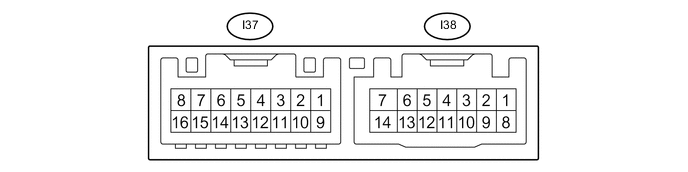
CHECK OUTER MIRROR CONTROL ECU ASSEMBLY RH
-
Disconnect the I38 outer mirror control ECU assembly RH connector.
-
Measure the voltage and resistance according to the value(s) in the table below.
Terminal No.
(Symbol)
Wiring Color Terminal Description Condition Specified Condition I38-5 (SIG) - I38-7 (GND) B - W-B ACC power supply Engine switch off (IG) Below 1 V Engine switch on (IG) 11 to 14 V I38-6 (CPUB) - I38-7 (GND) G - W-B Battery (ECU power source) Always 11 to 14 V I38-7 (GND) - Body ground W-B - Body ground Ground Always Below 1 Ω I38-14 (BDR) - I38-7 (GND) L - W-B Battery (ECU power source) Always 11 to 14 V -
Reconnect the I38 outer mirror control ECU RH connector.
-
Measure the voltage and resistance according to the value(s) in the table below.
Terminal No.
(Symbol)
Wiring Color Terminal Description Condition Specified Condition I37-3 (MR+) - Body ground G- Body ground Mirror retract motor output (retracting)
-
Engine switch on (ACC)
-
Outer rear view mirror assembly RH being retracted
11 to 14 V
-
Engine switch on (ACC)
-
Outer rear view mirror assembly RH stopped
Below 1 V I37-11 (MR-) - Body ground LG - Body ground Mirror retract motor output (returning)
-
Engine switch on (ACC)
-
Outer rear view mirror assembly LH retuning
11 to 14 V
-
Engine switch on (ACC)
-
Outer rear view mirror assembly LH stopped
Below 1 V I37-1 (RMVR) - Body ground R - Body ground Mirror motor output
-
Engine switch on (ACC)
-
Mirror surface stopped
Below 1 V
-
Engine switch on (ACC)
-
Mirror surface moving downward or left
Below 1 V
-
Engine switch on (ACC)
-
Mirror surface moving upward
11 to 14 V I37-9 (RMHR) - Body ground G - Body ground Mirror motor output
-
Engine switch on (ACC)
-
Mirror surface stopped
Below 1 V
-
Engine switch on (ACC)
-
Mirror surface moving upward or right
Below 1 V
-
Engine switch on (ACC)
-
Mirror surface moving left
11 to 14 V I37-10 (RM+R) - Body ground P - Body ground Mirror motor output
-
Engine switch on (ACC)
-
Mirror surface stopped
Below 1 V
-
Engine switch on (ACC)
-
Mirror surface moving upward or left
Below 1 V
-
Engine switch on (ACC)
-
Mirror surface moving downward or right
11 to 14 V I37-5 (RVC) - I37-14 (RE1)*1 B - R Mirror position sensor power supply Engine switch off Below 1 V Engine switch on (IG) 4.5 to 5.5V I37-6 (VSSR) - Body ground*1 SB - Body ground Vertical direction position sensor signal
-
Engine switch on (ACC)
-
Mirror surface moving upward or downward
Voltage fluctuates between 0 to 5 V I37-13 (HSSR) - Body ground*1 L - Body ground Horizontal direction position sensor signal
-
Engine switch on (ACC)
-
Mirror surface moving left or right
Voltage fluctuates between 0 to 5 V I37-4 (HTR+) - I37-12 (HTR-)*2 SB - L Mirror heater drive voltage
-
Engine switch on (IG)
-
Rear window defogger switch (mirror heater switch) off
Below 1 V
-
Engine switch on (IG)
-
Rear window defogger switch (mirror heater switch) on
11 to 14 V I38-2 (M1) - I38-7(GND)*1, *3 G - W-B Seat memory switch M1 signal
-
Engine switch on (IG)
-
Seat memory switch M1 on
11 to 14 V
-
Engine switch on (IG)
-
Seat memory switch M1 off
Below 1 V I38-3 (M2) - I38-7(GND)*1, *3 W - W-B Seat memory switch M2 signal
-
Engine switch on (IG)
-
Seat memory switch M2 on
11 to 14 V
-
Engine switch on (IG)
-
Seat memory switch M2 off
Below 1 V I38-4 (M3) - I38-7(GND)*1, *3 R - W-B Seat memory switch M3 signal
-
Engine switch on (IG)
-
Seat memory switch M3 on
11 to 14 V
-
Engine switch on (IG)
-
Seat memory switch M3 off
Below 1 V I38-1 (MM) - I38-7(GND)*1, *3 B - W-B Seat memory switch SET signal
-
Engine switch on (IG)
-
Seat memory switch SET on
11 to 14 V
-
Engine switch on (IG)
-
Seat memory switch SET off
Below 1 V
-
*1: w/ Memory
-
*2: w/ Mirror Heater
-
*3: for LHD
If the result is not as specified, the ECU may have a malfunction.
-
-
-
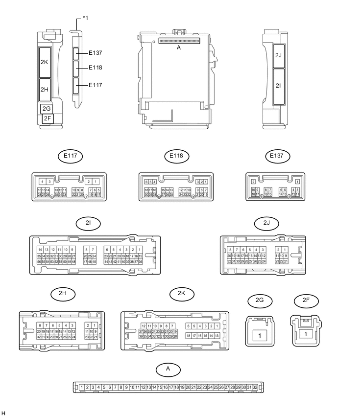
CHECK MAIN BODY ECU (MULTIPLEX NETWORK BODY ECU), COWL SIDE JUNCTION BLOCK LH
-
Remove the main body ECU (multiplex network body ECU) from the cowl side junction block LH .
-
for LHD: Click here
-
for RHD: Click here
-
-
Measure the voltage and resistance according to the value(s) in the table below.
Terminal No.
(Symbol)
Wiring Color Terminal Description Condition Specified Condition A-32 (IG) - Body ground - IG power supply Engine switch off Below 1 V Engine switch on (IG) 11 to 14 V A-30 (ACC) - Body ground - ACC power supply Engine switch off Below 1 V Engine switch on (ACC) 11 to 14 V A-31 (BECU) - Body ground - BECU power supply Always 11 to 14 V A-11 (GND1) - Body ground - Body ground Always Below 1 Ω -
Install the main body ECU (multiplex network body ECU) to the cowl side junction block LH.
-
for LHD: Click here
-
for RHD: Click here
-
-
Measure the voltage and resistance according to the value(s) in the table below.
Terminal No.
(Symbol)
Wiring Color Terminal Description Condition Specified Condition E117-14 (RET) - 2J-1 (GND) BE - W-B Mirror retract motor output (retracting)
-
Engine switch on (ACC)
-
Outer mirror switch assembly (mirror retract switch) on
Below 1 V
-
Engine switch on (ACC)
-
Outer mirror switch assembly (mirror retract switch) off
11 to 14 V E137-4 (MIRB) - E137-6 (MIRE) B - P Mirror surface adjust switch signal
-
Engine switch on (ACC)
-
Outer mirror switch assembly (mirror surface adjust switch) right
Below 2.7 V
-
Engine switch on (ACC)
-
Outer mirror switch assembly (mirror surface adjust switch) left
Below 4 V
-
Engine switch on (ACC)
-
Outer mirror switch assembly (mirror surface adjust switch) down
Below 3.5 V
-
Engine switch on (ACC)
-
Outer mirror switch assembly (mirror surface adjust switch) up
Below 1.7 V
-
Engine switch on (ACC)
-
Outer mirror switch assembly (mirror surface adjust switch) not pushed
11 to 14 V E137-5 (MIRS) - E137-6 (MIRE) W - P Mirror select switch signal
-
Engine switch on (ACC)
-
Outer mirror switch assembly (mirror select switch) L
11 to 14 V
-
Engine switch on (ACC)
-
Outer mirror switch assembly (mirror select switch) R
Below 2 V
-
Engine switch on (ACC)
-
Outer mirror switch assembly (mirror select switch) neutral
Below 1 V -
-