BACK DOOR REASSEMBLY
PROCEDURE
-
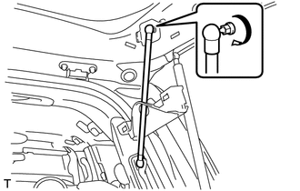
INSTALL BACK DOOR DAMPER ASSEMBLY (w/ Power Back Door)
-
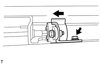
When reusing the back door damper assembly:
-
Install the back door damper assembly with the bolt.
- Torque:
- 7.5 N*m { 76 kgf*cm, 66 in.*lbf }
-
-
When installing a new back door damper assembly:
-
With closing the tail gate, install a new back door damper assembly with the bolt.
- Torque:
- 7.5 N*m { 76 kgf*cm, 66 in.*lbf }
-
-
-
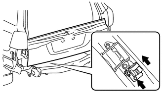
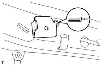
INSTALL TAIL GATE STAY SUB-ASSEMBLY LH
-
Clean the threaded surface on the vehicle body with a non-residue solvent.
-
Apply adhesive to the threads of the screws.
Adhesive Toyota Genuine Adhesive 1324, Three Bond 1324 or equivalent -
Using a T40 "TORX" wrench, install the 2 screws and tail gate stay.
-
-
INSTALL TAIL GATE STAY SUB-ASSEMBLY RH
Tech Tips
Use the same procedure described for the LH side.
-
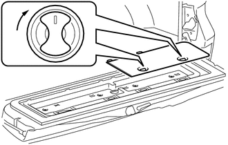
INSTALL LOWER TAIL GATE LOCK ASSEMBLY LH
-
w/o Power Back Door:
-
Using a T30 "TORX" wrench, install the 3 screws and lower tail gate lock assembly LH.
- Torque:
- 5.0 N*m { 51 kgf*cm, 44 in.*lbf }
-
-
w/ Power Back Door:
-
Using a T30 "TORX" wrench, install the 4 screws and lower tail gate lock assembly LH.
- Torque:
- 5.0 N*m { 51 kgf*cm, 44 in.*lbf }
-
Connect the connector.
-
-
-
INSTALL BACK DOOR REMOTE CONTROL ASSEMBLY
-
w/o Power Back Door:
-
Connect the left side cable.
-
Using a T30 "TORX" wrench, install the 2 screws and back door remote control assembly.
- Torque:
- 5.0 N*m { 51 kgf*cm, 44 in.*lbf }
-
-
w/ Power Back Door:
-
Connect the connector.
-
Using a T30 "TORX" wrench, install the 2 screws and back door remote control assembly.
- Torque:
- 5.0 N*m { 51 kgf*cm, 44 in.*lbf }
-
-
-
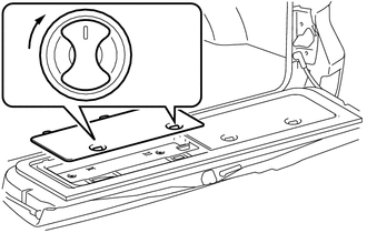
INSTALL LOWER TAIL GATE LOCK ASSEMBLY RH
-
w/o Power Back Door:
-
Connect the cable to the lower tail gate lock assembly RH.
-
Using a T30 "TORX" wrench, install the 3 screws and lower tail gate lock assembly RH.
- Torque:
- 5.0 N*m { 51 kgf*cm, 44 in.*lbf }
-
-
w/ Power Back Door:
-
Using a T30 "TORX" wrench, install the 4 screws and lower tail gate lock assembly RH.
- Torque:
- 5.0 N*m { 51 kgf*cm, 44 in.*lbf }
-
Connect the connector.
-
-
-
INSTALL BACK DOOR INSIDE HANDLE ASSEMBLY
-
Install the back door handle grommet.
-
Install the screw and back door inside handle assembly.
- Torque:
- 5.0 N*m { 51 kgf*cm, 44 in.*lbf }
-
-
INSTALL BACK DOOR TORSION BAR GUIDE
-
Attach the 2 claws to install the back door torsion bar guide.
-
-
INSTALL LOWER BACK DOOR TORSION BAR ASSEMBLY
-
Install the 4 bolts and lower back door torsion bar assembly.
- Torque:
- 7.5 N*m { 76 kgf*cm, 66 in.*lbf }
-
-
INSTALL SPARE TIRE
-
INSTALL REAR BUMPER ASSEMBLY
-
for Standard:
-
Install the rear bumper assembly Click here.
-
-
w/ Towing Hitch:
-
Install the rear bumper assembly Click here.
-
-
w/ Pintle Hook:
-
Install the rear bumper assembly Click here.
-
-
-
INSTALL REAR LICENSE LIGHT COVER (w/ Tire Carrier)
-
INSTALL LICENSE PLATE LIGHT ASSEMBLY (w/ Tire Carrier)
-
INSTALL NO. 2 BACK DOOR OUTSIDE GARNISH SUB-ASSEMBLY (w/ Tire Carrier)
-
INSTALL BACK DOOR TRIM PANEL ASSEMBLY
-
Attach the 16 clips to install the back door trim panel assembly.
-
Install the 4 bolts.
-
-
INSTALL BACK DOOR TRIM COVER RH
-
Install the back door trim cover RH as shown in the illustration.
-
-
INSTALL BACK DOOR TRIM COVER LH
-
Install the back door trim cover LH as shown in the illustration.
-
-
INSTALL REAR FLOOR MAT REAR SUPPORT PLATE
-
INSTALL BACK DOOR STAY ASSEMBLY LH
-
INSTALL BACK DOOR STAY ASSEMBLY RH
Tech Tips
Use the same procedure described for the LH side.
-
INSTALL REAR WASHER NOZZLE (w/ Rear Wiper)
-
INSTALL REAR SPOILER SUB-ASSEMBLY (w/ Rear Spoiler)
-
INSTALL BACK DOOR GLASS CHANNEL LH (w/o Power Back Door)
-
INSTALL BACK DOOR GLASS CHANNEL RH (w/o Power Back Door)
Tech Tips
Use the same procedure described for the LH side.
-
INSTALL BACK DOOR OUTSIDE GARNISH SUB-ASSEMBLY
-
INSTALL LOWER BACK DOOR STOPPER
-
Install the bolt and lower back door stopper.
-
-
INSTALL CUSHION
-
Install the 2 cushions.
-
-
INSTALL LIFT GATE WEATHERSTRIP
-
Attach the 25 clips to install the lift gate weatherstrip.
Note
Do not pull strongly on the lift gate weatherstrip as it may tear.
-
-
INSTALL REAR TELEVISION CAMERA ASSEMBLY (w/ Parking Assist Monitor System or Rear View Monitor System)
-
INSTALL BACK DOOR OPENER SWITCH ASSEMBLY
-
INSTALL LICENSE PLATE LIGHT LENS (for Standard)
-
INSTALL BACK DOOR CONTROL SWITCH (w/ Power Back Door)
-
INSTALL BACK DOOR LOCK PROTECTOR (w/ Power Back Door)
-
INSTALL BACK DOOR LOCK ASSEMBLY
-
INSTALL BACK DOOR LOCK COVER
-
INSTALL REAR WIPER MOTOR ASSEMBLY (w/ Rear Wiper)
-
INSTALL REAR WIPER MOTOR GROMMET (w/ Rear Wiper)
-
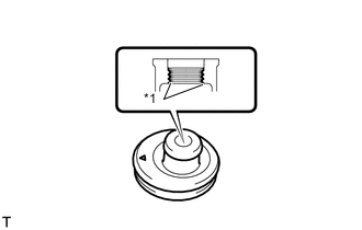
Text in Illustration *1 MP Grease Apply MP grease to the entire inner surface of the rear wiper motor grommet.
Tech Tips
Make sure that the hole does not get clogged with grease and the grooves in the grommet are filled with grease.
-
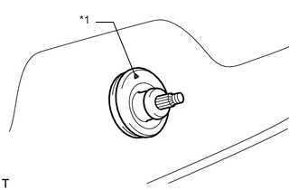
Text in Illustration *1 Position Mark Install the rear wiper motor grommet with the position mark facing upward as shown in the illustration.
-
-
INSTALL REAR WIPER ARM (w/ Rear Wiper)
-
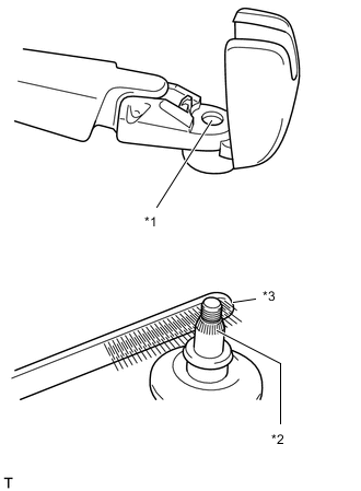
Text in Illustration *1 Wiper Arm Serration *2 Wiper Pivot Serration *3 Wire Brush Operate the rear wiper, and stop the rear wiper motor at the automatic stop position.
-
Clean the wiper arm serration and wiper pivot serration with a wire brush.
-
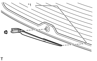
Text in Illustration *1 Defogger Line Set the head of the blade on the defogger line.
-
Install the nut and rear wiper arm.
- Torque:
- 5.5 N*m { 56 kgf*cm, 49 in.*lbf }
-
Close the cover.
-
-
INSTALL POWER BACK DOOR SENSOR ASSEMBLY LH (w/ Power Back Door)
-
INSTALL POWER BACK DOOR SENSOR ASSEMBLY RH (w/ Power Back Door)
Tech Tips
Use the same procedure described for the LH side.
-
INSTALL REAR ASSIST GRIP REINFORCEMENT (for Face to Face Seat Type)
-
Attach the 2 claws to install the rear assist grip reinforcement.
-
Install the 3 bolts.
-
-
INSTALL REAR HEADER SPEAKER ASSEMBLY (for 14 Speakers)
-
INSTALL BACK DOOR GARNISH
-
Attach the 14 clips to install the back door garnish.
-
-
INSTALL DOOR OPENING SWITCH SUB-ASSEMBLY (for Face to Face Seat Type)
-
INSTALL NO. 2 BACK DOOR SERVICE HOLE COVER (for Face to Face Seat Type)
-
Connect the connector.
-
Attach the 4 claws to install the No. 2 back door service hole cover.
-
-
INSTALL ASSIST GRIP (for Face to Face Seat Type)
-
Install the assist grip with the 2 screws.
-
-
INSTALL BACK DOOR SERVICE HOLE COVER RH (w/ Power Back Door)
-
Install the back door stay plate.
-
Pass the power back door rod through the hole of the back door service hole cover RH and install the rod with the bolt.
- Torque:
- 18 N*m { 184 kgf*cm, 13 ft.*lbf }
-
Move the back door to a half-open position so that the hole in the center of the back door service hole cover RH is aligned lengthwise with the power back door rod.
-
Attach the 2 clips and install the back door service hole cover RH.
Note
If the back door is in a fully-open position, the power back door rod will interfere with the hole of the back door service hole cover, so do not perform this operation with the back door in a fully open position.
-
-
INSTALL BACK DOOR SIDE GARNISH LH
-
Attach the 3 clips and 2 claws to install the back door side garnish LH.
-
-
INSTALL BACK DOOR SIDE GARNISH RH
-
w/o Power Back Door:
Tech Tips
Use the same procedure described for the LH side.
-
w/ Power Back Door:
-
Attach the clip and 4 claws to install the back door side garnish RH.
-
-
-
INSTALL CENTER STOP LIGHT ASSEMBLY
-
INSTALL CENTER BACK DOOR GARNISH
-
Attach the 5 clips and 4 claws to install the center back door garnish.
-
-
INSTALL LOWER BACK DOOR STOPPER CUSHION
-
Install the 2 lower back door stopper cushions with the 4 bolts.
-
-
INSTALL BACK DOOR GRIP
-
Attach the claw.
-
Install the back door grip with the 2 screws.
-
Attach the 5 claws to close the cover.
-
-
CONNECT CABLE TO NEGATIVE BATTERY TERMINAL
Note
When disconnecting the cable, some systems need to be initialized after the cable is reconnected Click here.
-
ADJUST REAR TELEVISION CAMERA ASSEMBLY
-
w/o Side Monitor System:
-
w/ Side Monitor System:
-