BACK DOOR ADJUSTMENT
PROCEDURE
-
INSPECT TAIL GATE PANEL SUB-ASSEMBLY (w/o Tire Carrier)
-
Check that the clearance measurements of areas A to B are within the standard range.
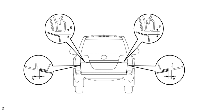
Standard Area Specified Condition Area Specified Condition A 3.35 to 6.35mm (0.132 to 0.250 in.) B 4.05 to 7.05mm (0.159 to 0.278 in.)
-
-
INSPECT TAIL GATE PANEL SUB-ASSEMBLY (w/ Tire Carrier)
-
Check that the clearance measurements of areas A to B are within the standard range.
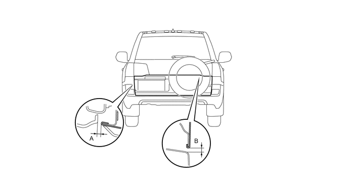
Standard Area Specified Condition Area Specified Condition A 3.35 to 6.35mm (0.132 to 0.250 in.) B 3.35 to 6.35mm (0.132 to 0.250 in.)
-
-
ADJUST TAIL GATE PANEL SUB-ASSEMBLY
-
Loosen the hinge bolts.
-
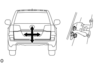
Adjust the tail gate by moving it up and down and left and right so that the dimensions are within the specified range.
-
Tighten the hinge bolts.
- Torque:
- 28 N*m { 286 kgf*cm, 21 ft.*lbf }
-
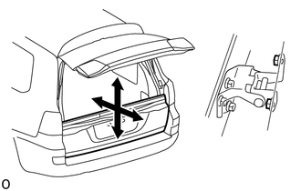
Loosen the hinge bolts.
-
Adjust the tail gate by moving it up and down and forward and backward so that the dimensions are within the specified range.
-
Tighten the hinge bolts.
- Torque:
- 31 N*m { 316 kgf*cm, 23 ft.*lbf }
-
-
ADJUST DOOR LOCK STRIKER
-
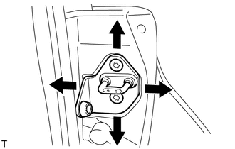
Using a T40 "TORX" socket, adjust the striker position by slightly loosening the striker mounting screws and hitting the striker with a plastic-faced hammer.
-
Using a T40 "TORX" socket, tighten the striker mounting screws after the adjustment.
- Torque:
- 12 N*m { 122 kgf*cm, 9 ft.*lbf }
-
-
INSPECT BACK DOOR PANEL SUB-ASSEMBLY
-
Check that the clearance measurements of areas A to G are within the standard range.
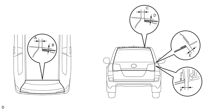
Standard Measurement Area Specified Condition Area Specified Condition A 4.7 to 7.7 mm (0.185 to 0.303 in.) D 1.5 to 4.5mm (0.059 to 0.177 in.) B 1.5 to 4.5mm (0.059 to 0.177 in.) E 3.2 to 6.2mm (0.126 to 0.244 in.) C 4.8 to 7.8mm (0.189 to 0.307 in.) F 3.5 to 6.5mm (0.138 to 0.256 in.)
-
-
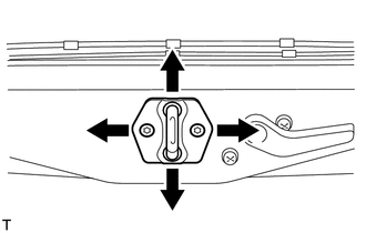
ADJUST REAR SWING GATE LOCK STRIKER
-
Check that the door fit and door linkages are adjusted correctly.
-
Using a T40 "TORX" socket, adjust the striker position by slightly loosening the striker mounting screws and hitting the striker with a plastic-faced hammer.
-
Using a T40 "TORX" socket, tighten the striker mounting screws after the adjustment.
- Torque:
- 23 N*m { 235 kgf*cm, 17 ft.*lbf }
-
-
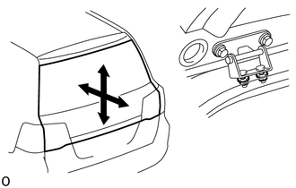
ADJUST BACK DOOR PANEL SUB-ASSEMBLY
-
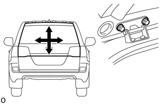
Loosen the hinge bolts.
-
Adjust the back door by moving it up and down and left and right so that the dimensions are within the specified range.
-
Tighten the hinge bolts.
- Torque:
- 19 N*m { 194 kgf*cm, 14 ft.*lbf }
-
Partially remove the roof headlining.
-
w/ Sliding Roof:
-
w/o Sliding Roof:
-
-
Loosen the hinge nuts.
-
Adjust the back door by moving it up and down and forward and backward so that the dimensions are within the specified range.
-
Tighten the hinge nuts.
- Torque:
- 19 N*m { 194 kgf*cm, 14 ft.*lbf }
-
Install the roof headlining.
-
w/ Sliding Roof:
-
w/o Sliding Roof:
-
-