TAIL GATE CLOSER SYSTEM Tail Gate Closer does not Operate
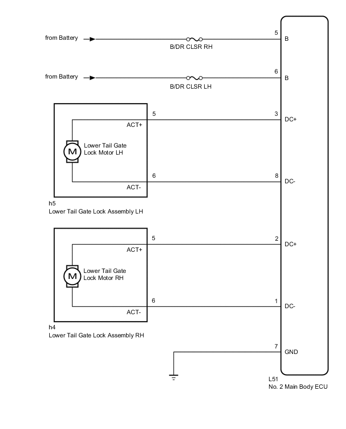
WIRING DIAGRAM
CAUTION / NOTICE / HINT
Note
Inspect the fuses for circuits related to this system before performing the following inspection procedure.
PROCEDURE
-
CHECK HARNESS AND CONNECTOR (NO. 2 MAIN BODY ECU - BATTERY AND BODY GROUND)
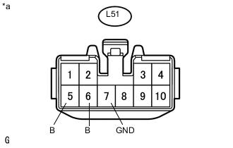
Text in Illustration *a Front view of wire harness connector
(to No. 2 Main Body ECU)
-
Disconnect the No. 2 main body ECU connector.
-
Measure the voltage according to the value(s) in the table below.
Standard Voltage Tester Connection Condition Specified Condition L51-5 (B) - Body ground Always 11 to 14 V L51-6 (B) - Body ground Always 11 to 14 V -
Measure the resistance according to the value(s) in the table below.
Standard Resistance Tester Connection Condition Specified Condition L51-7 (GND) - Body ground Always Below 1 Ω
NG 
REPAIR OR REPLACE HARNESS OR CONNECTOR
OK 
-
-
INSPECT LOWER TAIL GATE LOCK ASSEMBLY
-
for LH:
-
Remove the lower tail gate lock assembly LH Click here.
-
Inspect the lower tail gate lock assembly LH Click here.
-
-
for RH:
-
Remove the lower tail gate lock assembly RH Click here.
-
Inspect the lower tail gate lock assembly RH Click here.
Result Result Proceed to OK A NG (for LH) B NG (for RH) C -
B
REPLACE LOWER TAIL GATE LOCK ASSEMBLY LH Click here
C
REPLACE LOWER TAIL GATE LOCK ASSEMBLY RH Click here
A
-
-
CHECK HARNESS AND CONNECTOR (LOWER TAIL GATE LOCK ASSEMBLY - NO. 2 MAIN BODY ECU)
-
for LH:
-
Disconnect the h5 lower tail gate lock assembly LH connector.
-
Disconnect the L51 No. 2 main body ECU connector.
-
Measure the resistance according to the value(s) in the table below.
Standard Resistance Tester Connection Condition Specified Condition h5-5 (ACT+) - L51-3 (DC+) Always Below 1 Ω h5-6 (ACT-) - L51-8 (DC-) Always Below 1 Ω h5-5 (ACT+) - Body ground Always 10 kΩ or higher h5-6 (ACT-) - Body ground Always 10 kΩ or higher
-
-
for RH:
-
Disconnect the h4 lower tail gate lock assembly RH connector.
-
Disconnect the L51 No. 2 main body ECU connector.
-
Measure the resistance according to the value(s) in the table below.
Standard Resistance Tester Connection Condition Specified Condition h4-5 (ACT+) - L51-2 (DC+) Always Below 1 Ω h4-6 (ACT-) - L51-1 (DC-) Always Below 1 Ω h4-5 (ACT+) - Body ground Always 10 kΩ or higher h4-6 (ACT-) - Body ground Always 10 kΩ or higher
-
OK
REPLACE NO. 2 MAIN BODY ECU Click here
NG
REPAIR OR REPLACE HARNESS OR CONNECTOR
-