SLIDING ROOF SYSTEM Sliding Roof Control Switch Circuit
DESCRIPTION
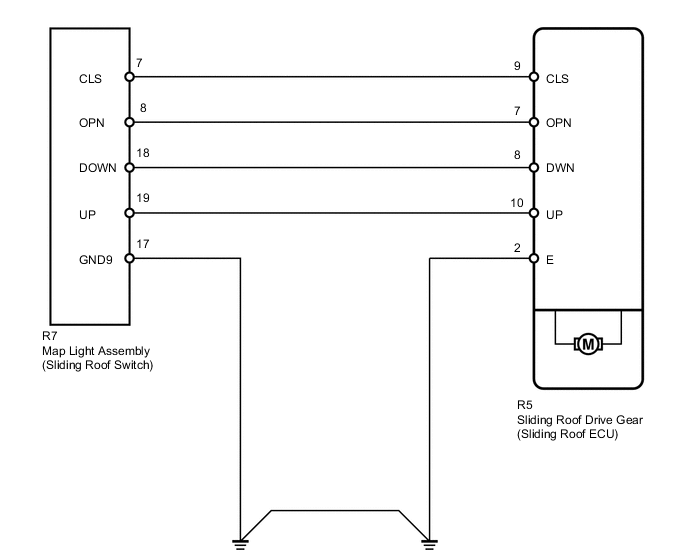
The sliding roof drive gear (sliding roof ECU) receives slide switch and tilt switch signals and drives its built-in motor.
WIRING DIAGRAM
PROCEDURE
-
PERFORM ACTIVE TEST USING INTELLIGENT TESTER (SLIDING ROOF OPERATION)
-
Select the Active Test, use the intelligent tester to generate a control command, and then check that the sliding roof slides open/closed and tilts up/down Click here.
Sliding Roof Tester Display Test Part Control Range Diagnostic Note Slide Roof Operate sliding roof SLIDE CLOSE/TILT UP CLOS/UP: Sliding roof SLIDE CLOSE or TILT UP operation occurs
OFF: Sliding roof is not operating
Be careful to avoid injuries as this test causes vehicle parts to move. Slide Roof Operate sliding roof SLIDE OPEN/TILT DOWN OPEN/DWN: Sliding roof SLIDE OPEN or TILT DOWN operation occurs
OFF: Sliding roof is not operating
Be careful to avoid injuries as this test causes vehicle parts to move. OK Sliding roof operates normally.
NG 
REPLACE SLIDING ROOF DRIVE GEAR SUB-ASSEMBLY (SLIDING ROOF ECU) Click here
OK 
-
-
READ VALUE USING INTELLIGENT TESTER (SLIDING ROOF SWITCH)
-
Use the Data List to check if the sliding roof switch is functioning properly Click here.
Sliding Roof Item Measurement Item/Range Normal Condition Diagnostic Note Open Switch Sliding roof switch open signal/ON or OFF ON: OPEN switch is pressed
OFF: OPEN switch is not pressed
- Close Switch Sliding roof switch close signal/ON or OFF ON: CLOSE switch is pressed
OFF: CLOSE switch is not pressed
- Up Switch Sliding roof switch tilt up signal/ON or OFF ON: UP switch is pressed
OFF: UP switch is not pressed
- Down Switch Sliding roof switch tilt down signal/ON or OFF ON: DOWN switch is pressed
OFF: DOWN switch is not pressed
- OK When the switch is operating, the intelligent tester should display as shown in the table.
OK
REPLACE SLIDING ROOF DRIVE GEAR SUB-ASSEMBLY (SLIDING ROOF ECU) Click here
NG
-
-
INSPECT MAP LIGHT ASSEMBLY (SLIDING ROOF SWITCH)
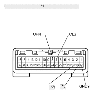
*1 Component without harness connected: (Map Light Assembly) *2 UP *3 DOWN
-
Remove the map light Click here.
-
Measure the resistance according to the value(s) in the table below.
Standard Resistance Tester Connection Switch Condition Specified Condition 19 (UP) - 17 (GND9) UP switch is pressed Below 1 Ω 19 (UP) - 17 (GND9) UP switch is not pressed 10 kΩ or higher 18 (DOWN) - 17 (GND9) DOWN switch is pressed Below 1 Ω 18 (DOWN) - 17 (GND9) DOWN switch is not pressed 10 kΩ or higher 8 (OPN) - 17 (GND9) OPEN switch is pressed Below 1 Ω 8 (OPN) - 17 (GND9) OPEN switch is not pressed 10 kΩ or higher 7 (CLS) - 17 (GND9) CLOSE switch is pressed Below 1 Ω 7 (CLS) - 17 (GND9) CLOSE switch is not pressed 10 kΩ or higher
NG
REPLACE MAP LIGHT ASSEMBLY (SLIDING ROOF SWITCH) Click here
OK
-
-
CHECK HARNESS AND CONNECTOR (SLIDING ROOF DRIVE GEAR - MAP LIGHT)
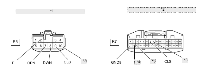
*1 Front view of wire harness connector: (to Sliding Roof Drive Gear) *2 Front view of wire harness connector: (to Map Light Assembly) *3 UP *4 DOWN
-
Disconnect the R5 drive gear connector.
-
Disconnect the R7 map light connector.
-
Measure the resistance according to the value(s) in the table below.
Standard Resistance Tester Connection Condition Specified Condition R5-10 (UP) - R7-19 (UP) Always Below 1 Ω R5-8 (DWN) - R7-18 (DOWN) Always Below 1 Ω R5-7 (OPN) - R7-8 (OPN) Always Below 1 Ω R5-9 (CLS) - R7-7 (CLS) Always Below 1 Ω R7-17 (GND9) - Body ground Always Below 1 Ω R5-2 (E) - Body ground Always Below 1 Ω R5-10 (UP) or R7-19 (UP) - Body ground Always 10 kΩ or higher R5-8 (DWN) or R7-18 (DOWN) - Body ground Always 10 kΩ or higher R5-7 (OPN) or R7-8 (OPN) - Body ground Always 10 kΩ or higher R5-9 (CLS) or R7-7 (CLS) - Body ground Always 10 kΩ or higher
OK
REPLACE SLIDING ROOF DRIVE GEAR SUB-ASSEMBLY (SLIDING ROOF ECU) Click here
NG
REPAIR OR REPLACE HARNESS OR CONNECTOR
-