SLIDING ROOF SYSTEM TERMINALS OF ECU
-
CHECK SLIDING ROOF DRIVE GEAR SUB-ASSEMBLY (SLIDING ROOF ECU)
-
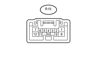
Disconnect the R15 siding roof drive gear sub-assembly (sliding roof ECU) connector.
-
Measure the resistance and voltage according to the value(s) in the table below.
Terminal No. (Symbols) Wiring Color Terminal Description Condition Specified Condition R15-8 (B) - R15-12 (E) LA-L - W-B +B power supply Always 11 to 14 V R15-1 (IG) - R15-12 (E) B - W-B Power supply Engine switch off Below 1 V Engine switch on (IG) 11 to 14 V R15-7 (OPN) - R15-12 (E) P - W-B Sliding roof motor open OPEN switch off 10 kΩ or higher OPEN switch on Below 1 Ω R15-5 (CLS) - R15-12 (E) G - W-B Sliding roof motor close CLOSE switch off 10 kΩ or higher CLOSE switch on Below 1 Ω R15-4 (UP) - R15-12 (E) R - W-B Sliding roof motor up UP switch off 10 kΩ or higher UP switch on Below 1 Ω R15-6 (DWN) - R15-12 (E) GR - W-B Sliding roof motor down DOWN switch off 10 kΩ or higher DOWN switch on Below 1 Ω R15-12 (E) - Body ground W-B - Body ground Ground Always Below 1 Ω
-