WINDOW DEFOGGER SYSTEM(for Double Swing Out Type) Rear Window Defogger System does not Operate
DESCRIPTION
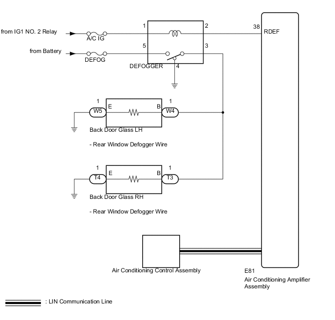
When the rear window defogger switch is turned on, a rear window defogger activation request signal is sent via the LIN communication line to the air conditioning amplifier. Then the air conditioning amplifier operates the rear window defogger. When the on signal from the switch is received, the defogger relay (DEFOG) is operated for 15 minutes. Also, if the off signal from the switch is received within 15 minutes, the defogger relay (DEFOG) operation is stopped.
WIRING DIAGRAM
CAUTION / NOTICE / HINT
Note
-
Inspect the fuses for circuits related to this system before performing the following inspection procedure.
-
Since the window defogger system has functions that use LIN communication, first confirm that there is no malfunction in the communication system by inspecting the LIN communication functions in accordance with the "How to Proceed with Troubleshooting" procedures. Then, conduct the following inspection procedure.
PROCEDURE
-
PERFORM ACTIVE TEST USING INTELLIGENT TESTER (DEFOGGER RELAY)
-
Select the Active Test using the intelligent tester to generate a control command, and then check that the rear window defogger operates.
Air Conditioner Tester Display Test part Control Range Diagnostic Note Defogger Relay (Rear) Rear window defogger relay operation OFF or ON - OK Rear window defogger relay operates normally.
NG 
INSPECT DEFOGGER RELAY (DEFOG) Click here
OK 
-
-
REPLACE AIR CONDITIONING CONTROL ASSEMBLY
-
Temporarily replace the air conditioning control assembly with a new or normally function one Click here.
NEXT
-
-
CHECK REAR WINDOW DEFOGGER SYSTEM
-
Turn the ignition switch ON.
-
Check that pressing the defogger switch illuminates the indicator and warms the rear window surface.
-
Check that after approximately 15 minutes, the indicator light turns off and the rear window defogger deactivates.
OK Rear window defogger system functioning.
OK 
END (AIR CONDITIONING CONTROL ASSEMBLY IS DEFECTIVE)
NG
REPLACE AIR CONDITIONING AMPLIFIER ASSEMBLY Click here
-
-
INSPECT DEFOGGER RELAY (DEFOG)
-
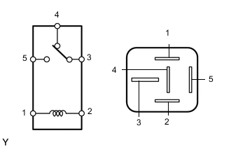
Remove the defogger relay from the engine room relay block.
-
Measure the resistance according to the value(s) in the table below.
Standard Resistance Tester Connection Condition Specified Condition 3 - 4 Battery voltage is not applied to terminals 1 and 2 Below 1 Ω 3 - 5 10 kΩ or higher 3 - 4 Battery voltage is applied to terminals 1 and 2 10 kΩ or higher 3 - 5 Below 1 Ω
NG
REPLACE DEFOGGER RELAY
OK
-
-
CHECK HARNESS AND CONNECTOR (DEFOGGER RELAY - BATTERY AND AIR CONDITIONING AMPLIFIER ASSEMBLY)
-
Remove the defogger relay from the engine room relay block.
-
Disconnect the E81 air conditioning amplifier assembly connector.
-
Measure the voltage according to the value(s) in the table below.
Standard Voltage Tester Connection Condition Specified Condition Defogger relay terminal 1 - Body ground Ignition switch ON 11 to 14 V Defogger relay terminal 5 - Body ground Always 11 to 14 V -
Measure the resistance according to the value(s) in the table below.
Standard Resistance Tester Connection Condition Specified Condition Defogger relay terminal 2 - E81-38 (RDEF) Always Below 1 Ω
NG
REPAIR OR REPLACE HARNESS OR CONNECTOR
OK
-
-
CHECK HARNESS AND CONNECTOR (DEFOGGER RELAY - REAR WINDOW DEFOGGER AND BODY GROUND)
-
Remove the defogger relay from the engine room relay block.
-
Disconnect the W4, W5, T3 and T4 defogger wire connectors.
-
Measure the resistance according to the value(s) in the table below.
Standard Voltage Tester Connection Condition Specified Condition Defogger relay terminal 3 - W4-1 (B) Always Below 1 Ω W5-1 (E) - Body ground Defogger relay terminal 3 - T3-1 (B) T4-1 (E) - Body ground Defogger relay terminal 4 - Body ground W4-1 (B) - Body ground Always 10 kΩ or higher T3-1 (B) - Body ground
NG
REPAIR OR REPLACE HARNESS OR CONNECTOR
OK
-
-
CHECK BACK DOOR GLASS (REAR WINDOW DEFOGGER WIRE)
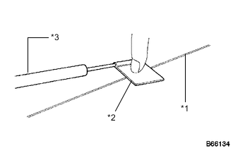
Text in Illustration *1 Defogger Wire *2 Tin Foil *3 Tester Probe Note
-
When cleaning the glass, wipe the glass along the wire using a soft, dry cloth. Take care not to damage the defogger wires.
-
Do not use detergents or glass cleaners that have abrasive ingredients.
-
When measuring voltage, wrap a piece of tin foil around the tip of the negative (-) tester probe and press the foil against the wire with your finger as shown in the illustration.
-
Turn the ignition switch to ON.
-
Turn the defogger switch on.
-
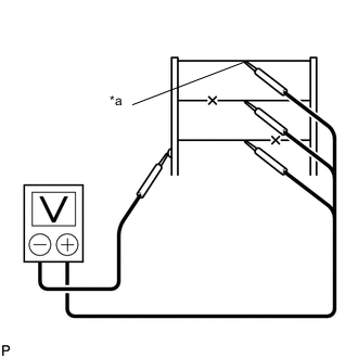
Text in Illustration *a Center 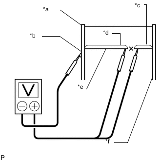
Text in Illustration *a Ground Side *b Foil Strip *c Approximately 10 V *d 0 V *e Broken Wire *f Battery Side Measure the voltage at the center of each defogger wire as shown in the illustration.
Standard Voltage Voltage Diagnosis Approx. 5 V Wire is not broken Approx. 10 or 0 V Wire is broken Tech Tips
If there is approximately 10 V, the wire may be faulty between the center of the wire and the wire end on the ground side. If there is no voltage, the wire may be faulty between the center of the wire and the wire end on the battery side.
-
Place the voltmeter positive (+) lead against the defogger wire on the battery side.
-
Place the voltmeter negative (-) lead with the foil strip against the wire on the ground side.
-
Slide the positive (+) lead from the battery side to the ground side.
-
The point where the voltage drops from approximately 10 V to 0 V is where the defogger wire is broken.
Tech Tips
If the defogger wire is not broken, the voltmeter indicates 10 V at the positive (+) end of the defogger wire and gradually decreases to approximately 0 V as the meter probe moves to the other end.
Result Result Proceed to Wire is broken (for LH) A Wire is broken (for RH) B Wire is not broken C
A
REPLACE BACK DOOR GLASS LH (REAR WINDOW DEFOGGER WIRE) Click here
B
REPLACE BACK DOOR GLASS RH (REAR WINDOW DEFOGGER WIRE) Click here
C
REPLACE AIR CONDITIONING AMPLIFIER ASSEMBLY Click here
-