WINDSHIELD DEICER SYSTEM TERMINALS OF ECU
-
CHECK AIR CONDITIONING AMPLIFIER ASSEMBLY (w/ Rear Heater)
-
Disconnect the E36 air conditioning amplifier assembly connector.
-
Measure the resistance and voltage according to the value(s) in the table below.
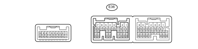
Terminal No. (Symbol) Wiring Color Terminal Description Condition Specified Condition E36-5 (IG+) - E36-1 (GND) G - W-B Power source (IG) Ignition switch ON 11 to 14 V Ignition switch off Below 1 V E36-6 (+B1) - E36-1 (GND) R - W-B Power source Always 11 to 14 V E36-7 (+B2) - E36-1 (GND) R - W-B Power source Always 11 to 14 V E36-1 (GND) - Body ground W-B - Body ground Ground Always Below 1 Ω
-
If the result is not as specified, there may be a malfunction on the wire harness side.
-
-
Reconnect the E36 air conditioning amplifier assembly connector.
-
Measure the voltage according to the value(s) in the table below.
Terminal No. (Symbol) Wiring Color Terminal Description Condition Specified Condition E36-23 (FDEF) - E36-1 (GND) GR - W-B Deicer relay Ignition switch ON and deicer switch off 11 to 14 V Ignition switch ON and deicer switch on Below 1 V
-
-
CHECK AIR CONDITIONING AMPLIFIER ASSEMBLY (w/o Rear Heater)
-
Disconnect the E81 air conditioning amplifier assembly connector.
-
Measure the resistance and voltage according to the value(s) in the table below.
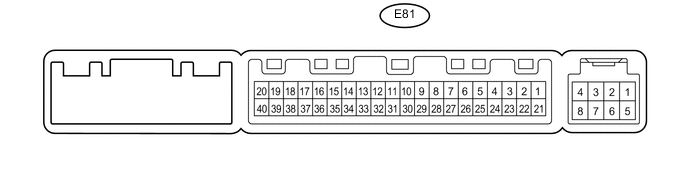
Terminal No. (Symbol) Wiring Color Terminal Description Condition Specified Condition E81-1 (IG+) - E81-14 (GND) G - W-B Power source (IG) Ignition switch ON 11 to 14 V Ignition switch off Below 1 V E81-21 (+B1) - E81-14 (GND) R - W-B Power source Always 11 to 14 V E81-14 (GND) - Body ground W-B - Body ground Ground Always Below 1 Ω
-
If the result is not as specified, there may be a malfunction on the wire harness side.
-
-
Reconnect the E81 air conditioning amplifier assembly connector.
-
Measure the voltage according to the value(s) in the table below.
Terminal No. (Symbol) Wiring Color Terminal Description Condition Specified Condition E81-40 (FDEF) - E81-14 (GND) GR - W-B Deicer relay Ignition switch ON and deicer switch off 11 to 14 V Ignition switch ON and deicer switch on Below 1 V
-
-
CHECK AIR CONDITIONING CONTROL ASSEMBLY (w/o Navigation System)

-
Disconnect the F10 air conditioning control assembly connector.
-
Measure the resistance and voltage according to the value(s) in the table below.
Terminal No. (Symbol) Wiring Color Terminal Description Condition Specified Condition F10-7 (IG+) - F10-1 (GND) G - W-B Power source (IG) Ignition switch ON 11 to 14 V Ignition switch off Below 1 V F10-1 (GND) - Body ground W-B - Body ground Ground Always Below 1 Ω
-
If the result is not as specified, there may be a malfunction on the wire harness side.
-
-
-
MULTI-MEDIA MODULE RECEIVER ASSEMBLY (w/ Navigation System)
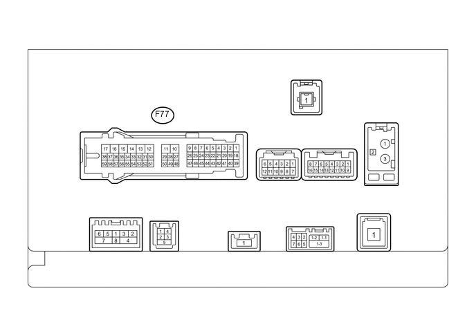
Terminal No. (Symbol) Wiring Color Terminal Description Condition Specified Condition F77-17 (+B1) - F77-12 (GND1) R - W-B Power source Always 11 to 14 V F77-12 (GND1) - Body ground W-B - Body ground Ground Always Below 1 Ω F77-15 (IG) - F77-12 (GND1) G - W-B Power source (IG) Ignition switch ON 11 to 14 V Ignition switch off Below 1 V F77-16 (ACC1) - F77-12 (GND1) GR - W-B Power source (ACC) Ignition switch ACC 11 to 14 V Ignition switch off Below 1 V F77-35 (UIND) R UART communication signal - - F77-36 (UPSW) P UART communication signal - - F77-1 (CANH) P CAN communication signal - - F77-2 (CANL) B CAN communication signal - - -
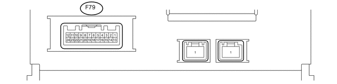
MULTI-DISPLAY ASSEMBLY (w/ Navigation System)
Terminal No. (Symbol) Wiring Color Terminal Description Condition Specified Condition F79-12 (+B2) - F79-13 (GND1) R - BR Power source Always 11 to 14 V F79-13 (GND1) - Body ground BR - Body ground Ground Always Below 1 Ω F79-23 (IG) - F79-13 (GND1) G - BR Power source (IG) Ignition switch ON 11 to 14 V Ignition switch off Below 1 V F79-24 (ACC) - F79-13 (GND1) GR - BR Power source (ACC) Ignition switch ACC 11 to 14 V Ignition switch off Below 1 V F79-3 (UPSW) P UART communication signal - - F79-4 (UIND) R UART communication signal - -