PROCEDURE
- Click here
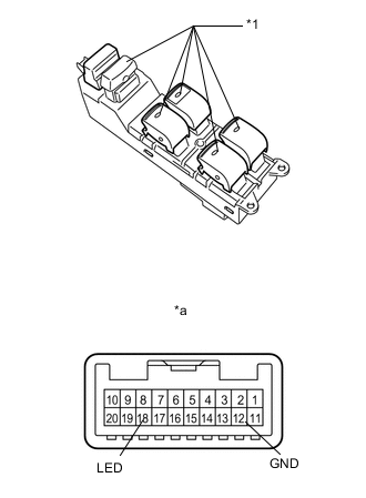
INSPECT MULTIPLEX NETWORK MASTER SWITCH ASSEMBLY (for Models with Jam Protection Function on 4 Windows)
-

for LHD:
Check that the LED illuminates.
-
Apply battery voltage to the master switch and check that the LED illuminates.
OK Measurement Condition Specified Condition Battery positive (+) → 18 (LED)
Battery negative (-) → 12 (GND)
LED illuminates
-
If the result is not as specified, replace the multiplex network master switch assembly.
Table 1. Text in Illustration *1 LED *a Component without harness connected:
(Multiplex Network Master Switch Assembly)
-
-
-
for RHD:
Check that the LED illuminates.
-
Apply battery voltage to the master switch and check that the LED illuminates.
OK Measurement Condition Specified Condition Battery positive (+) → 18 (LED)
Battery negative (-) → 12 (GND)
LED illuminates
-
If the result is not as specified, replace the multiplex network master switch assembly.
Table 2. Text in Illustration *1 LED *a Component without harness connected:
(Multiplex Network Master Switch Assembly)
-
-
-
- Click here
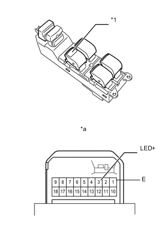
INSPECT MULTIPLEX NETWORK MASTER SWITCH ASSEMBLY (for Models with Jam Protection Function on Driver Door Window Only)
-
for LHD:
Check that the LED illuminates.
-
Apply battery voltage to the master switch and check that the LED illuminates.
OK Measurement Condition Specified Condition Battery positive (+) → 3 (LED+)
Battery negative (-) → 1 (E)
LED illuminates
-
If the result is not as specified, replace the multiplex network master switch assembly.
Table 3. Text in Illustration *1 LED *a Component without harness connected:
(Multiplex Network Master Switch Assembly)
-
-
-

for RHD:
Check that the LED illuminates.
-
Apply battery voltage to the master switch and check that the LED illuminates.
OK Measurement Condition Specified Condition Battery positive (+) → 3 (LED+)
Battery negative (-) → 1 (E)
LED illuminates
-
If the result is not as specified, replace the multiplex network master switch assembly.
Table 4. Text in Illustration *1 LED *a Component without harness connected:
(Multiplex Network Master Switch Assembly)
-
-
-