POWER WINDOW CONTROL SYSTEM(for Models with Jam Protection Function on Driver Door Window Only) Rear Power Window LH does not Operate with Rear Power Window Switch LH
DESCRIPTION
-
If the manual up/down function does not operate, there may be a malfunction in the rear power window regulator switch, power window rear regulator motor LH, multiplex network master switch assembly, harness or connector.
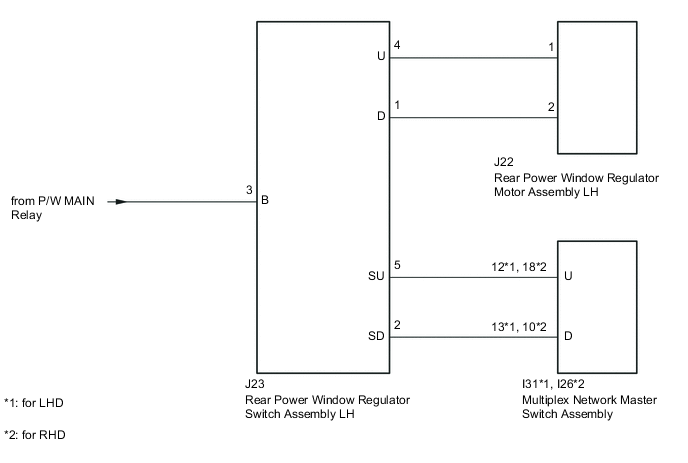
WIRING DIAGRAM
PROCEDURE
-
INSPECT REAR POWER WINDOW REGULATOR SWITCH ASSEMBLY LH
-
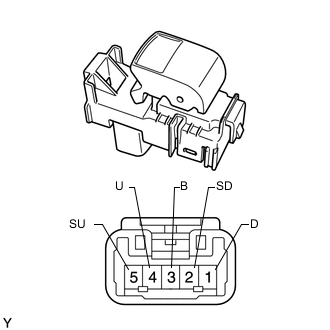
Remove the rear power window regulator switch assembly LH Click here.
-
Measure the resistance according to the value(s) in the table below.
Standard Resistance Tester Connection Switch Condition Specified Condition 4 (U) - 3 (B) UP Below 1 Ω 2 (SD) - 1 (D) 5 (SU) - 4 (U) OFF Below 1 Ω 2 (SD) - 1 (D) 5 (SU) - 4 (U) DOWN Below 1 Ω 3 (B) - 1 (D)
NG 
REPLACE REAR POWER WINDOW REGULATOR SWITCH ASSEMBLY LH Click here
OK 
-
-
INSPECT REAR POWER WINDOW REGULATOR MOTOR ASSEMBLY LH
-
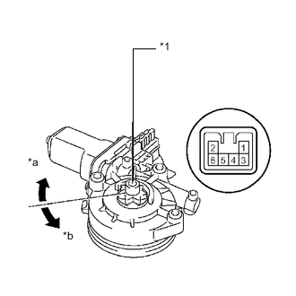
Text in Illustration *1 Motor Gear *a Counterclockwise *b Clockwise Remove the rear window regulator motor assembly LH Click here.
-
Apply battery voltage to the motor connector according to the table below.
OK Measurement Condition Specified Condition Battery positive (+) → 1
Battery negative (-) → 2
Motor gear rotates clockwise Battery positive (+) → 2
Battery negative (-) → 1
Motor gear rotates counterclockwise
NG
REPLACE REAR POWER WINDOW REGULATOR MOTOR ASSEMBLY LH Click here
OK
-
-
CHECK HARNESS AND CONNECTOR (REAR POWER WINDOW REGULATOR SWITCH LH - BATTERY)
-
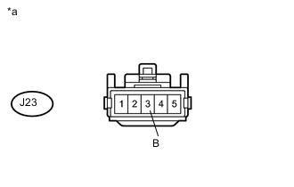
Text in Illustration *a Front view of wire harness connector
(to Rear Power Window Regulator Switch Assembly LH)
Disconnect the J23 rear power window regulator switch assembly LH connector.
-
Measure the voltage according to the value(s) in the table below.
Standard Voltage Tester Connection Switch Condition Specified Condition J23-3 (B) - Body ground Ignition switch ON 11 to 14 V
NG
REPAIR OR REPLACE HARNESS OR CONNECTOR
OK
-
-
CHECK HARNESS AND CONNECTOR (REAR POWER WINDOW REGULATOR SWITCH LH - REAR POWER WINDOW REGULATOR MOTOR LH)
-
Disconnect the J23 rear power window regulator switch assembly LH connector.
-
Disconnect the J22 rear power window regulator motor assembly LH connector.
-
Measure the resistance according to the value(s) in the table below.
Standard Resistance Tester Connection Condition Specified Condition J23-4 (U) - J22-1 Always Below 1 Ω J23-1 (D) - J22-2 Always Below 1 Ω J23-4 (U) or J22-1 - Body ground Always 10 KΩ or higher J23-1 (D) or J22-2 - Body ground Always 10 KΩ or higher
NG
REPAIR OR REPLACE HARNESS OR CONNECTOR
OK
-
-
CHECK HARNESS AND CONNECTOR (REAR POWER WINDOW REGULATOR SWITCH LH - MULTIPLEX NETWORK MASTER SWITCH)
-
Disconnect the J23 rear power window regulator switch assembly LH connector.
-
Disconnect the I31*1 or I26*2 multiplex network master switch assembly connector.
-
*1: for LHD
-
*2: for RHD
-
-
Measure the resistance according to the value(s) in the table below.
Standard Resistance for LHD Tester Connection Condition Specified Condition J23-5 (SU) - I31-12 (U) Always Below 1 Ω J23-2 (SD) - I31-13 (D) Always Below 1 Ω J23-5 (SU) or I30-12 (U) - Body ground Always 10 kΩ or higher J23-2 (SD) or I30-13 (D) - Body ground Always 10 kΩ or higher for RHD Tester Connection Condition Specified Condition J23-5 (SU) - I26-18 (U) Always Below 1 Ω J23-2 (SD) - I26-10 (D) Always Below 1 Ω J23-5 (SU) or I26-18 (U) - Body ground Always 10 kΩ or higher J23-2 (SD) or I26-10 (D) - Body ground Always 10 kΩ or higher
OK
REPLACE MULTIPLEX NETWORK MASTER SWITCH ASSEMBLY Click here
NG
REPAIR OR REPLACE HARNESS OR CONNECTOR
-