FRONT CONSOLE BOX(w/o Cool Box) REMOVAL
CAUTION / NOTICE / HINT
Tech Tips
-
Use the same procedure for RHD and LHD vehicles.
-
The procedure listed below is for LHD vehicles.
PROCEDURE
-
REMOVE NO. 2 INSTRUMENT PANEL FINISH PANEL CUSHION
-
for Type A:
-
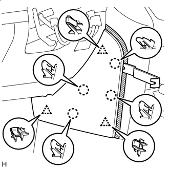

Protective Tape Put protective tape around the No. 2 instrument panel finish panel cushion.
-
Using a moulding remover B, detach the 4 claws and 3 clips and remove the No. 2 instrument panel finish panel cushion.
-
-
for Type B:
-
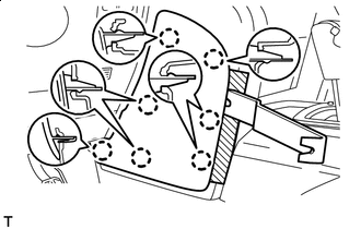
Protective Tape Put protective tape around the No. 2 instrument panel finish panel cushion.
-
Using a moulding remover, detach the 7 claws and remove the No. 2 instrument panel finish panel cushion.
-
-
-
REMOVE LOWER INSTRUMENT PANEL PAD SUB-ASSEMBLY LH
-
for Type A:
-
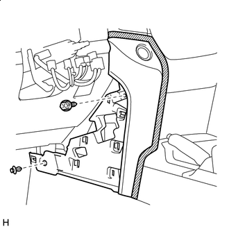
Protective Tape Put protective tape around the lower instrument panel pad sub-assembly LH.
-
Remove the clip and screw.
-
Detach the 11 claws and guide.
-
Disconnect the connector and detach the clamps and remove the lower instrument panel pad sub-assembly LH.
-
-
for Type B:
-
Protective Tape Put protective tape around the lower instrument panel pad sub-assembly LH.
-
Remove the clip and screw.
-
Detach the 8 claws and 2 guides and remove the lower instrument panel pad sub-assembly LH.
-
-
-
REMOVE NO. 1 INSTRUMENT PANEL FINISH CUSHION
-
for Type A:
-
Protective Tape Put protective tape around the No. 1 instrument panel finish cushion.
-
Using a moulding remover B, detach the 4 claws and 3 clips and remove the No. 2 instrument panel finish cushion.
-
-
for Type B:
-
Protective Tape Put protective tape around the No. 1 instrument panel finish cushion.
-
Using a moulding remover, detach the 7 claws and remove the No. 2 instrument panel finish cushion.
-
-
-
REMOVE LOWER INSTRUMENT PANEL PAD SUB-ASSEMBLY RH
-
for Type A:
-
Protective Tape Put protective tape around the lower instrument panel pad sub-assembly RH.
-
Remove the clip and screw.
-
Detach the 11 claws and guide and remove the lower instrument panel pad sub-assembly RH.
-
-
for Type B:
-
Protective Tape Put protective tape around the lower instrument panel pad sub-assembly RH.
-
Remove the clip and screw.
-
Detach the 7 claws and remove the lower instrument panel pad sub-assembly RH.
-
-
-
REMOVE SHIFT LEVER KNOB SUB-ASSEMBLY
-
for Type A, Automatic Transmission:
-
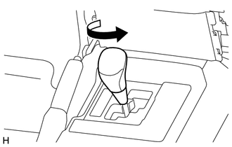
Twist the shift lever knob sub-assembly in the direction indicated by the arrow and remove it.
-
-
for Type A, Manual Transmission:
-
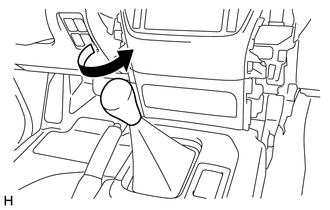
Twist the shift lever knob sub-assembly in the direction indicated by the arrow and remove it.
-
-
for Type B:
-
Twist the shift lever knob sub-assembly in the direction indicated by the arrow and remove it.
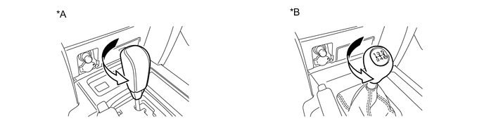
*A for Automatic Transmission *B for Manual Transmission
-
-
-
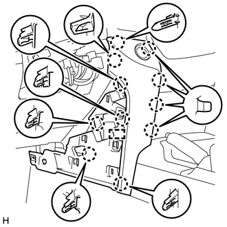
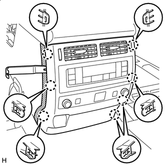
REMOVE LOWER CENTER INSTRUMENT CLUSTER FINISH PANEL SUB-ASSEMBLY
-
for Type A:
-
Protective Tape Put protective tape around the lower center instrument cluster finish panel sub-assembly.
-
Detach the 6 claws and remove the lower center instrument cluster finish panel sub-assembly.
-
-
for Type B:
-
Protective Tape Put protective tape around the lower center instrument cluster finish panel sub-assembly.
-
Detach the 7 claws.
-
Disconnect the connectors and remove the lower center instrument cluster finish panel sub-assembly.
-
-
-
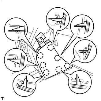
REMOVE CONSOLE CUP HOLDER BOX SUB-ASSEMBLY
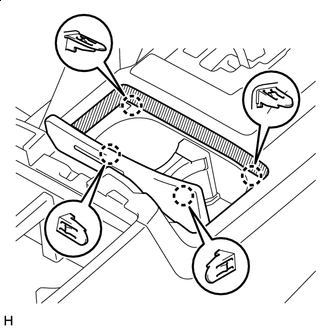
Protective Tape
-
Put protective tape around the lower console cup holder box sub-assembly.
-
Detach the 4 claws and remove the console cup holder box sub-assembly.
-
-
REMOVE UPPER CONSOLE PANEL (for Type A)
-
for Automatic Transmission:
-
Protective Tape Put protective tape around the upper console panel.
-
Detach the 8 claws and 5 clips.
-
Disconnect the connectors and remove the upper console panel.
-
-
for Manual Transmission:
-
Protective Tape Put protective tape around the upper console panel.
-
Detach the 8 claws and 5 clips.
-
Disconnect the connectors and remove the upper console panel.
-
-
-
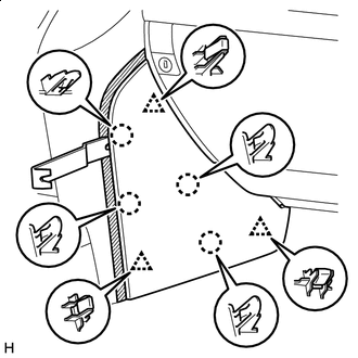
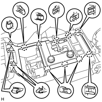
REMOVE REAR UPPER CONSOLE PANEL SUB-ASSEMBLY
Protective Tape
-
Put protective tape around the upper rear console panel sub-assembly.
-
Detach the 4 claws, clip and 3 guides and remove the upper rear console panel sub-assembly.
-
-
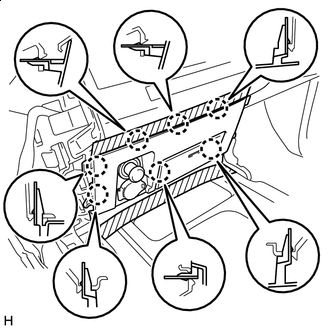
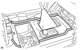
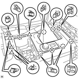
REMOVE UPPER CONSOLE PANEL SUB-ASSEMBLY
-
for Type A:
-
Protective Tape Put protective tape around the upper console panel sub-assembly.
-
Detach the 8 claws and 4 clips and remove the upper console panel sub-assembly.
-
-
for Type B:
-
Protective Tape Put protective tape around the upper console panel sub-assembly.
-
Detach the 14 claws.
-
Detach the 14 claws. (b) Disconnect the connectors and remove the upper console panel sub-assembly.
-
-
-
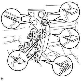
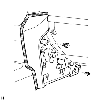
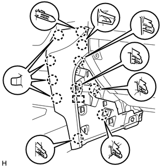
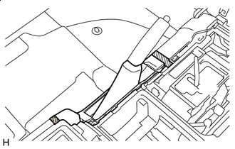
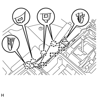
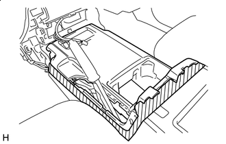
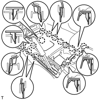
REMOVE REAR CONSOLE END PANEL SUB-ASSEMBLY
Protective Tape
-
Put protective tape around the rear console end panel sub-assembly.
-
Using a moulding remover B, detach the 7 claws.
-
Disconnect the connectors and detach the clamps and remove the rear console end panel sub-assembly.
-
-
REMOVE TELEMATICS TRANSCEIVER (w/ Telematics Transceiver)
-
REMOVE NO. 1 TELEPHONE BRACKET (w/ Telematics Transceiver)
-
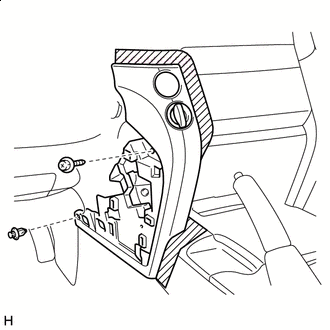
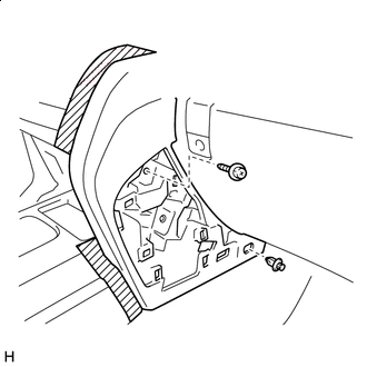
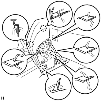
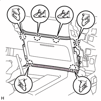
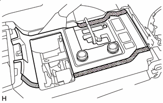
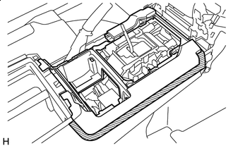
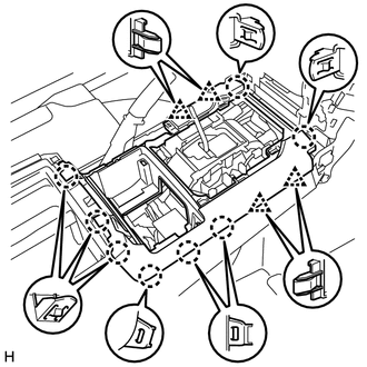
REMOVE REAR CONSOLE BOX SUB-ASSEMBLY
-
Remove the 2 screws and 4 bolts.
-
Detach the 2 claws and remove the rear console box sub-assembly.
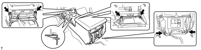
*a Screw *b Bolt
-