INSTRUMENT PANEL SAFETY PAD INSTALLATION
CAUTION / NOTICE / HINT
Tech Tips
-
Use the same procedure for RHD and LHD vehicles.
-
The procedure listed below is for LHD vehicles.
-
A bolt without a torque specification is shown in the standard bolt chart Click here.
PROCEDURE
-
INSTALL INSTRUMENT PANEL SAFETY PAD ASSEMBLY
-
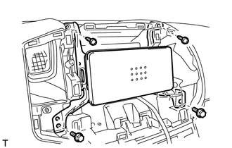
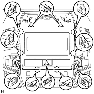
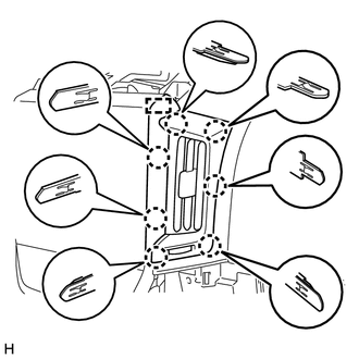
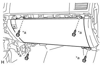
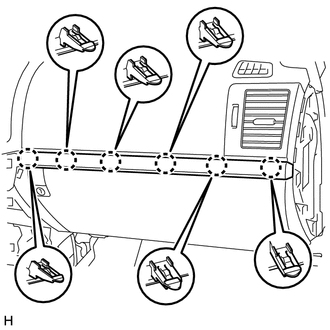
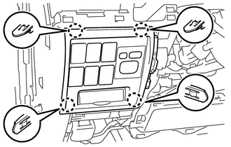
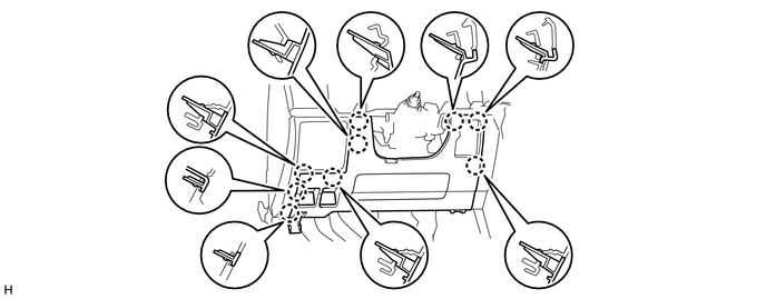
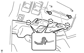
Install the instrument panel safety pad assembly with the 6 bolts <E>, 2 nuts <F> and 2 bolts <B>.
-
Install the 2 passenger airbag installation bolts <D>.
- Torque:
- 20 N*m { 204 kgf*cm, 15 ft.*lbf }
-
Connect the connectors.
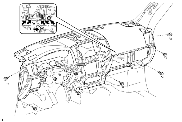
Text in Illustration *a Bolt <E> *b Nut <F> *c Bolt <B> *d Passenger Airbag Installation Bolt <D> *e Connector *f Passenger Airbag Connector -
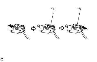
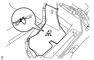
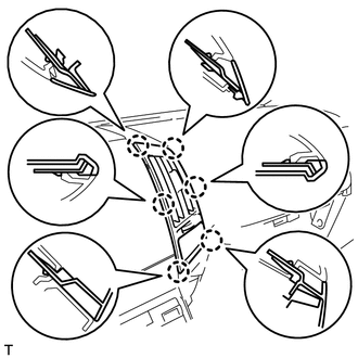
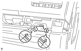
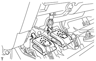
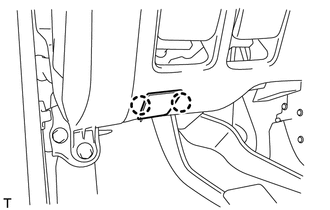
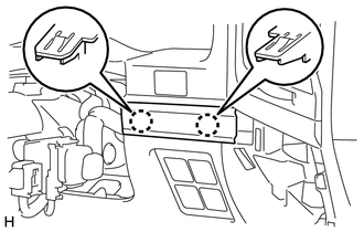
Text in Illustration *a Lock Slider *b Lock Position Connect the passenger airbag connector.
Note
When handling the passenger airbag connector, take care not to damage the airbag wire harness.
-
Check that the lock slider is in the lock position.
-
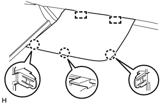
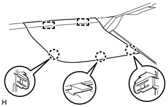
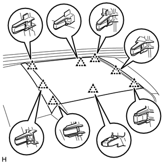
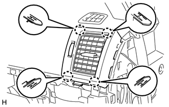
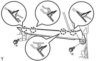
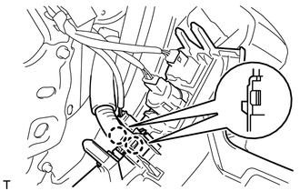
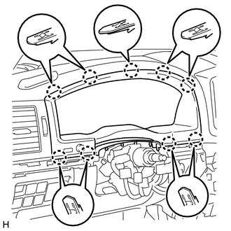
Connect the connectors and attach the clamps.
-
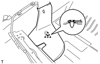
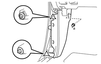
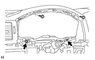
Connect the wire harness with the bolt.
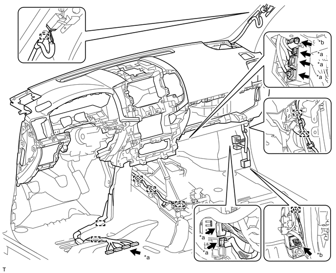
Text in Illustration *a Connector *b Bolt -
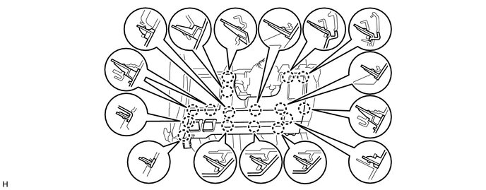
Connect the connectors and attach the clamps.
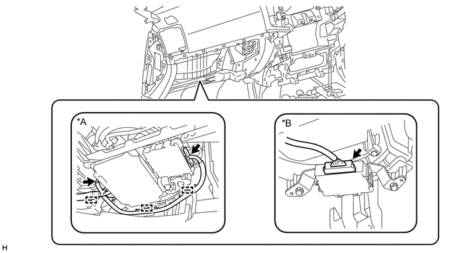
Text in Illustration *A w/ Multi-terrian Monitor System *B w/ TOYOTA Parking Assist-sensor System
-
-
INSTALL REAR NO. 4 AIR DUCT (w/ Rear Air Duct)
-
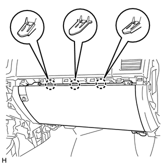
Attach the clip to install the rear No. 4 air duct.
-
-
INSTALL REAR NO. 2 AIR DUCT (w/ Rear Air Duct)
-
Attach the clip to install the rear No. 2 air duct.
-
-
INSTALL CENTER INSTRUMENT CLUSTER FINISH PANEL SUB-ASSEMBLY
-
w/o Wireless Charger:
-
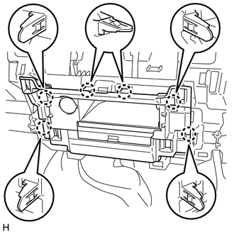
Connect the connectors.
-
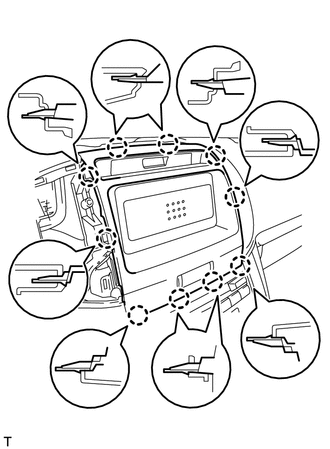
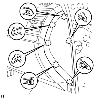
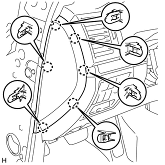
Attach the 6 claws to install the center instrument cluster finish panel sub-assembly.
-
-
w/ Wireless Charger:
-
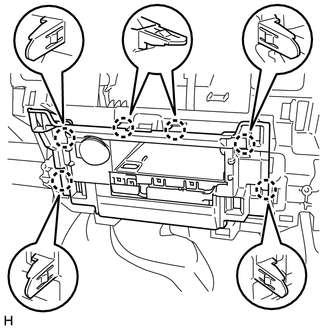
Connect the connectors.
-
Attach the 6 claws to install the center instrument cluster finish panel sub-assembly.
-
-
-
INSTALL FRONT NO. 2 SPEAKER ASSEMBLY
Tech Tips
Use the same procedure for the RH and LH sides Click here.
-
INSTALL FRONT NO. 4 SPEAKER ASSEMBLY (w/ Front Center Speaker)
-
INSTALL NO. 1 INSTRUMENT PANEL SPEAKER PANEL SUB-ASSEMBLY
-
Attach the 2 guides.
-
Attach the 3 claws to install the No. 1 instrument panel speaker panel sub-assembly.
-
-
INSTALL NO. 2 INSTRUMENT PANEL SPEAKER PANEL SUB-ASSEMBLY
-
Attach the 2 guides.
-
Attach the 3 claws to install the No. 2 instrument panel speaker panel sub-assembly.
-
-
INSTALL NO. 1 SPEAKER OPENING COVER ASSEMBLY
-
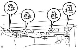
Attach the 8 clips to install the No. 1 speaker opening cover assembly.
-
-
INSTALL FRONT PILLAR GARNISH LH
-
INSTALL FRONT PILLAR GARNISH RH
-
INSTALL ASSIST GRIP SUB-ASSEMBLY
-
INSTALL MULTI-MEDIA MODULE RECEIVER ASSEMBLY (w/ Navigation System)
-
INSTALL AIR CONDITIONING CONTROL ASSEMBLY (w/o Navigation System)
-
INSTALL MULTI-DISPLAY ASSEMBLY (w/ Navigation System)
-
INSTALL RADIO TUNER OPENING COVER (w/o Radio Receiver)
-
Install the radio tuner opening cover with the 2 bolts and 2 screws.
- Torque:
- 12 N*m { 122 kgf*cm, 9 ft.*lbf }
-
-
INSTALL RADIO RECEIVER ASSEMBLY (for Radio Receiver Type)
-
INSTALL RADIO AND DISPLAY RECEIVER ASSEMBLY (for Radio and Display Type)
-
INSTALL NO. 1 CENTER INSTRUMENT CLUSTER FINISH PANEL (w/o Navigation System)
-
for Type A:
-
Connect the connector.
-
Attach the 8 claws and 3 clips to install the No. 1 center instrument cluster finish panel.
-
-
for Type B:
-
Connect the connector.
-
Attach the 10 claws to install the No. 1 center instrument cluster finish panel.
-
-
-
INSTALL NO. 3 INSTRUMENT PANEL REGISTER ASSEMBLY
-
for Type A:
-
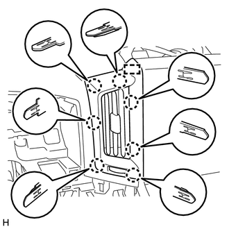
Attach the guide and 7 claws to install the No. 3 instrument panel register assembly.
-
-
for Type B:
-
Attach the 6 claws to install the No. 3 instrument panel register assembly.
-
-
-
INSTALL NO. 4 INSTRUMENT PANEL REGISTER ASSEMBLY
-
for Type A:
-
Attach the guide and 7 claws to install the No. 4 instrument panel register assembly.
-
-
for Type B:
-
Attach the 6 claws to install the No. 4 instrument panel register assembly.
-
-
-
INSTALL NO. 2 INSTRUMENT PANEL REGISTER ASSEMBLY
-
Attach the 4 claws to install the No. 2 instrument panel register assembly.
-
-
INSTALL LOWER NO. 2 INSTRUMENT PANEL FINISH PANEL
-
Connect the connector.
-
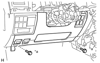
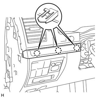
Attach the 3 claws to install the lower No. 2 instrument panel finish panel.
-
Text in Illustration *a Screw <C> Install the 4 screws <C>.
-
-
INSTALL INSTRUMENT PANEL BOX DOOR KNOB
Tech Tips
Use the same procedure for both instrument panel box door knobs.
-
Attach the 2 claws to install the instrument panel box door knob.
-
-
INSTALL NO. 3 INSTRUMENT CLUSTER FINISH PANEL GARNISH
-
Attach the 6 claws to install the No. 3 instrument cluster finish panel garnish.
-
-
INSTALL LOWER INSTRUMENT PANEL (w/o Passenger Side Knee Airbag)
Text in Illustration *a Bolt <B>
-
Attach the 4 claws to install the lower instrument panel.
-
Install the 2 bolts <B>.
-
-
INSTALL LOWER NO. 2 INSTRUMENT PANEL AIRBAG ASSEMBLY (w/ Passenger Side Knee Airbag)
-
INSTALL COWL SIDE TRIM BOARD RH
Text in Illustration *a Cap Nut
-
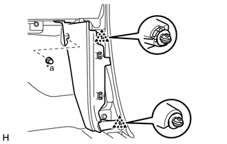
Attach the 2 clips to install the cowl side trim board RH.
-
Install the cap nut.
-
-
INSTALL NO. 2 INSTRUMENT PANEL UNDER COVER SUB-ASSEMBLY (w/ Floor Under Cover)
-
Connect the connector.
-
Attach the 3 guides.
-
Attach the 4 claws to install the No. 2 instrument panel under cover sub-assembly.
-
-
INSTALL FRONT DOOR SCUFF PLATE RH
-
INSTALL INSTRUMENT SIDE PANEL RH
-
w/ Airbag Cut Off Switch:
-
Connect the connector.
-
-
Attach the 6 claws to install the instrument side panel RH.
-
-
INSTALL NO. 1 INSTRUMENT PANEL REGISTER ASSEMBLY

-
Attach the 4 claws to install the No. 1 instrument panel register assembly.
-
-
INSTALL LOWER INSTRUMENT PANEL SUB-ASSEMBLY (w/o Driver Side Knee Airbag)
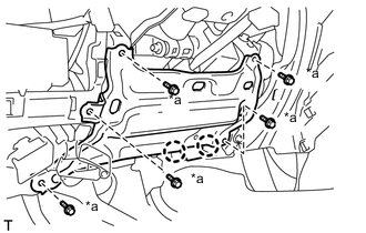
Text in Illustration *a Bolt <B>
-
Attach the 2 claws and connect the DLC3.
-
Install the lower instrument panel sub-assembly with the 5 bolts.
-
-
INSTALL LOWER NO. 1 INSTRUMENT PANEL AIRBAG ASSEMBLY (w/ Driver Side Knee Airbag)
-
INSTALL NO. 1 SWITCH HOLE BASE
-
Connect the connectors.
-
Attach the 4 claws to install the No. 1 switch hole base.
-
-
INSTALL LOWER NO. 1 INSTRUMENT PANEL FINISH PANEL
-
Connect the connectors.
-
Attach the 2 claws to connect the 2 control cables.
-
for Automatic Air Conditioning System:
-
Attach the 2 claws to install the room temperature sensor.
-
-
w/ Driver Side Knee Airbag:
-
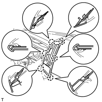
Attach the 16 claws to install the lower No. 1 instrument panel finish panel.
-
-
w/o Driver Side Knee Airbag:
-
Attach the 9 claws to install the lower No. 1 instrument panel finish panel.
-
-
Text in Illustration *a Bolt <B> Install the 2 bolts <B>.
-
Attach the 2 claws to close the hole cover.
-
-
INSTALL COWL SIDE TRIM BOARD LH
Text in Illustration *a Cap Nut
-
Attach the 2 clips to install the cowl side trim board LH.
-
Install the cap nut.
-
-
INSTALL NO. 1 INSTRUMENT PANEL UNDER COVER SUB-ASSEMBLY (w/ Floor Under Cover)
Text in Illustration *a Screw <A>
-
Connect the connector.
-
Attach the 3 claws to install the No. 1 instrument panel under cover sub-assembly.
-
Install the 2 screws <A>.
-
-
INSTALL FRONT DOOR SCUFF PLATE LH
-
INSTALL COMBINATION METER ASSEMBLY
-
Connect the connectors.
-
Install the combination meter assembly with the 4 screws.
-
-
INSTALL NO. 2 INSTRUMENT CLUSTER FINISH PANEL SUB-ASSEMBLY
-
Connect the connector.
-
Attach the 9 claws to install the No. 2 instrument cluster finish panel sub-assembly.
-
-
INSTALL NO. 2 INSTRUMENT CLUSTER FINISH PANEL GARNISH
-
Attach the 2 claws to install the No. 2 instrument cluster finish panel garnish.
-
-
INSTALL NO. 1 INSTRUMENT CLUSTER FINISH PANEL GARNISH
-
Attach the 3 claws to install the No. 1 instrument cluster finish panel garnish.
-
-
INSTALL INSTRUMENT SIDE PANEL LH
-
Attach the 6 claws to install the instrument side panel LH.
-
-
INSTALL REAR CONSOLE BOX SUB-ASSEMBLY (w/o Cool Box)
-
INSTALL COOLING BOX ASSEMBLY (w/ Cool Box)
-
INSTALL LOWER CONSOLE BOX (w/o Console Box Lid)
-
INSTALL HEADLIGHT DIMMER SWITCH ASSEMBLY
-
INSTALL FRONT SEAT ASSEMBLY LH
-
for Manual Seat:
-
for Power Seat:
-
-
INSTALL FRONT SEAT ASSEMBLY RH
-
for Manual Seat:
-
for Power Seat:
-
for Bench Seat Type:
-
-
CONNECT CABLE TO NEGATIVE BATTERY TERMINAL
Note
When disconnecting the cable, some systems need to be initialized after the cable is reconnected Click here.
-
CHARGE REFRIGERANT (w/ Cool Box)
-
WARM UP ENGINE (w/ Cool Box)
-
CHECK FOR REFRIGERANT GAS LEAK (w/ Cool Box)
-
ENABLE AUTOAWAY/RETURN FUNCTION (for Power Tilt and Power Telescopic Steering Column)
-
Restore the autoaway/return function setting to the previous condition by changing the customize parameter Click here.
-
-
CHECK SRS WARNING LIGHT