WIRELESS CHARGING SYSTEM Wireless Charger Power Source Circuit
DESCRIPTION
This is the power source circuit to operate the mobile wireless charger cradle assembly.
WIRING DIAGRAM
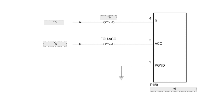
| *a | MPX-B NO.2 |
| *b | from BATTERY |
| *c | from ACC Relay |
| *d | Mobile Wireless Charger Cradle Assembly |
CAUTION / NOTICE / HINT
Note
Inspect the fuses for circuits related to this system before performing the following inspection procedure.
PROCEDURE
-
CHECK HARNESS AND CONNECTOR (MOBILE WIRELESS CHARGERCRADLE ASSEMBLY - BATTERY AND BODY GROUND)
-
Disconnect the mobile wireless charger cradle assembly connector.
-
Measure the resistance according to the value(s) in the table below.
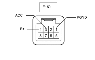
Standard Resistance Tester Connection Condition Specified Condition E150-1 (PGND) - Body ground Always Below 1 Ω -
Measure the voltage according to the value(s) in the table below.
Standard Voltage Tester Connection Switch Condition Specified Condition E150-4 (B+) - Body ground Power switch off 11 to 14 V E150-3 (ACC) - Body ground Power switch on (ACC) 11 to 14 V Power switch off Below 1 V
OK 
PROCEED TO NEXT SUSPECTED AREA SHOWN IN PROBLEM SYMPTOMS TABLE Click here
NG
REPAIR OR REPLACE HARNESS OR CONNECTOR
-