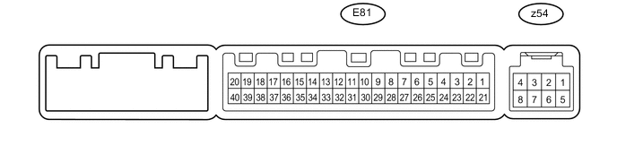
AIR CONDITIONING SYSTEM(for Manual Air Conditioning System) TERMINALS OF ECU
-
CHECK AIR CONDITIONING AMPLIFIER ASSEMBLY
-
Disconnect the E81 air conditioning amplifier assembly connector.
-
Measure the voltage and resistance according to the value(s) in the table below.
Terminal No. (Symbol) Wiring Color Terminal Description Condition Specified Condition E81-21 (+B1) - E81-14 (GND) R - W-B Battery power source Always 11 to 14 V E81-1 (IG+) - E81-14 (GND) G - W-B Ignition power supply Ignition switch ON 11 to 14 V Ignition switch off Below 1 V E81-14 (GND) - Body ground W-B - Body ground Ground Always Below 1 Ω
-
If the result is not as specified, there may be a malfunction on the wire harness side.
-
-
Reconnect the E81 air conditioning amplifier assembly connector.
-
Measure the voltage, resistance and waveform according to the value(s) in the table below.
Terminal No. (Symbol) Wiring Color Terminal Description Condition Specified Condition E81-8 (LOCK) - E81-35 (SG-5) L - G Compressor lock sensor signal Engine idling
Blower switch LO level
A/C switch on (magnet clutch on)
Pulse generation
(see waveform 1)
E81-35 (SG-5) - Body ground G - Body ground Ground for compressor lock sensor signal Always Below 1 Ω E81-13 (SG-2) - Body ground G - Body ground Ground for pressure sensor Always Below 1 Ω E81-17 (AC1) - Body ground L - Body ground Air conditioning operation request signal Engine idling
Blower switch LO level
A/C switch off
11 to 14 V Engine idling
Blower switch LO level
A/C switch on
Below 1 V E81-27 (ACT) - Body ground G - Body ground Magnet clutch operation permission signal Engine idling
Blower switch LO level
A/C switch off or A/C switch on (magnet clutch off)
11 to 14 V Engine idling
Blower switch LO level
A/C switch on (magnet clutch on)
Below 1 V E81-5 (TAM) - E81-13 (SG-2) V - G Ambient temperature sensor signal Ignition switch ON
Ambient temperature 25°C (77°F)
1.6 to 1.8 V Ignition switch ON
Ambient temperature 50°C (122°F)
0.5 to 0.7 V E81-30 (S5-1) - E81-13 (SG-2) LG - G Power supply for pressure sensor Ignition switch ON 4.5 to 5.5 V E81-9 (PRE) - E81-13 (SG-2) R - G Air conditioning pressure sensor signal Engine idling
Blower switch LO level
A/C switch on
0.63 to 4.72 V Engine idling
Blower switch LO level
A/C switch off
0.63 to 4.72 V E81-20 (MGC) - E81-14 (GND) R - W-B Magnet clutch operation signal Engine idling
Blower switch LO level
A/C switch on (magnet clutch on permitted)
Below 1 V Engine idling
Blower switch LO level
A/C switch off or on (magnet clutch on not permitted)
11 to 14 V E81-23 (BLW) - E81-14 (GND) R - W-B Blower motor control signal Ignition switch ON
Blower switch LO level
Pulse generation
(see waveform 2)
E81-37 (LIN1) - E81-14 (GND) Y - W-B LIN communication signal Ignition switch ON Pulse generation E81-25 (ALT) - Body ground R - Body ground Generator signal Engine idling Pulse generation E81-3 (PTC1) - Body ground* W - Body ground PTC heater relay operation signal Engine idling
Set temperature MAX. HOT
Engine coolant temperature below 65°C (149°F)
Ambient temperature below 10°C (50°F)
Blower switch off → LO level
Below 1 V → 11 to 14 V E81-22 (PTC2) - Body ground* R - Body ground E81-4 (PTC3) - Body ground* R - Body ground z54-4 (B BUS) - z54-2 (BUS G) - Power supply for BUS IC Ignition switch ON 11 to 14 V z54-5 (SGA) - Body ground - Ground for No. 1 cooler thermistor Always Below 1 Ω z54-2 (BUS G) - Body ground - Ground for BUS IC Always Below 1 Ω z54-6 (TEA) - z54-5 (SGA) - No. 1 cooler thermistor signal Ignition switch ON
Evaporator temperature 15°C (59°F)
1.4 to 1.8 V z54-3 (BUS) - z54-2 (BUS G) - BUS IC control signal Ignition switch ON Pulse generation
-
*: w/ PTC Heater
-
If the result is not as specified, the air conditioning amplifier assembly may have a malfunction.
-
-
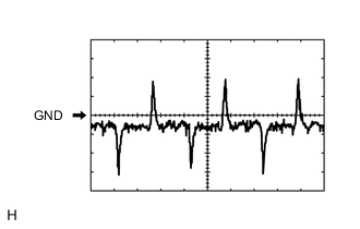
Using an oscilloscope, check waveform 1.
Compressor Lock Sensor Signal Item Content Terminal No. (Symbol) E81-8 (LOCK) - E81-35 (SG-5) Tool Setting 200 mV/DIV., 10 ms/DIV. Condition Engine idling
Blower switch LO level
A/C switch on (magnet clutch on)
Tech Tips
When the rear blower level is increased, the duty ratio changes accordingly.
-
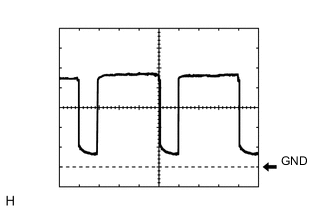
Using an oscilloscope, check waveform 2.
Blower Motor Control Signal Item Content Terminal No. (Symbol) E81-23 (BLW) - E81-14 (GND) Tool Setting 1 V/DIV., 500 μs/DIV. Condition Ignition switch ON
Blower switch LO level
Tech Tips
When the blower level is increased, the duty ratio changes accordingly.
-
-
CHECK AIR CONDITIONING CONTROL ASSEMBLY

-
Disconnect the F10 air conditioning control assembly connector.
-
Measure the resistance and voltage according to the value(s) in the table below.
Terminal No. (Symbol) Wiring Color Terminal Description Condition Specified Condition F10-7 (IG+) - F10-1 (GND) G - W-B Ignition power supply Ignition switch ON 11 to 14 V Ignition switch off Below 1 V F10-1 (GND) - Body ground W-B - Body ground Ground Always Below 1 Ω
-
If the result is not as specified, there may be a malfunction on the wire harness side.
-
-