AIR CONDITIONING SYSTEM(for Automatic Air Conditioning System) Back-up Power Source Circuit
DESCRIPTION
The back-up power source circuit for the air conditioning amplifier assembly is shown below. Power is supplied even when turning the ignition switch off and is used for diagnostic trouble code memory, etc.
WIRING DIAGRAM
-
w/ Rear Heater:
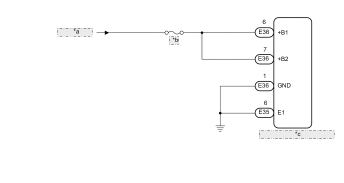
*a from Battery *b A/C *c Air Conditioning Amplifier Assembly -
w/o Rear Heater:
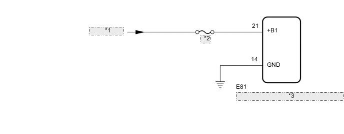
*1 from Battery *2 A/C *3 Air Conditioning Amplifier Assembly
CAUTION / NOTICE / HINT
Note
Inspect the fuses for circuits related to this system before performing the following inspection procedure.
PROCEDURE
-
CHECK HARNESS AND CONNECTOR (AIR CONDITIONING AMPLIFIER ASSEMBLY - BATTERY AND BODY GROUND)
-
w/ Rear Heater:
-
Disconnect the air conditioning amplifier assembly connectors.
-
Measure the resistance according to the value(s) in the table below.
Standard Resistance Tester Connection Condition Specified Condition E35-6 (E1) - Body ground Always 11 to 14 V E36-1 (GND) - Body ground Always 11 to 14 V -
Measure the voltage according to the value(s) in the table below.
Standard Voltage Tester Connection Condition Specified Condition E36-6 (+B1) - Body ground Always 11 to 14 V E36-7 (+B2) - Body ground Always 11 to 14 V
-
-
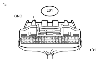
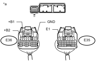
Text in Illustration *a Rear view of wire harness connector
(to Air Conditioning Amplifier Assembly)
w/o Rear Heater:
-
Disconnect the air conditioning amplifier assembly connector.
-
Measure the resistance according to the value(s) in the table below.
Standard Resistance Tester Connection Condition Specified Condition E81-14 (GND) - Body ground Always 11 to 14 V -
Measure the voltage according to the value(s) in the table below.
Standard Voltage Tester Connection Condition Specified Condition E81-21 (+B1) - Body ground Always 11 to 14 V
-
OK 
PROCEED TO NEXT CIRCUIT INSPECTION SHOWN IN PROBLEM SYMPTOMS TABLE Click here
NG
REPAIR OR REPLACE HARNESS OR CONNECTOR
-