AIR CONDITIONING SYSTEM(for Automatic Air Conditioning System) Back-up Power Source Circuit
DESCRIPTION
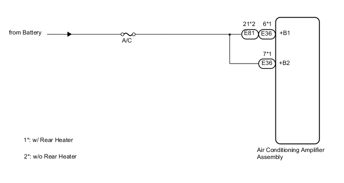
The back-up power source circuit for the air conditioning amplifier assembly is shown below. Power is supplied even when turning the engine switch off and is used for diagnostic trouble code memory, etc.
WIRING DIAGRAM
PROCEDURE
-
INSPECT FUSE (A/C)
-
Remove the A/C fuse from the cowl side junction block LH.
-
Measure the resistance according to the value(s) in the table below.
Standard Resistance Tester Connection Condition Specified Condition A/C fuse Always Below 1 Ω
NG 
REPLACE FUSE
OK 
-
-
CHECK HARNESS AND CONNECTOR (AIR CONDITIONING AMPLIFIER - BATTERY)
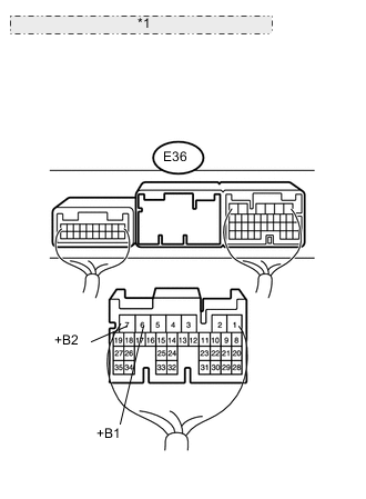
*1 Rear view of wire harness connector: (to Air Conditioning Amplifier Assembly)
-
w/ Rear Heater
-
Disconnect the E36 amplifier connector.
-
Measure the voltage according to the value(s) in the table below.
Standard Voltage Tester Connection Condition Specified Condition E36-6 (+B1) - Body ground Always 11 to 14 V E36-7 (+B2) - Body ground
-
-
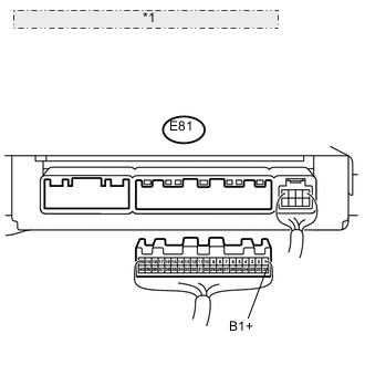
*1 Rear view of wire harness connector: (to Air Conditioning Amplifier Assembly) w/o Rear Heater
-
Disconnect the E81amplifier connector.
-
Measure the voltage according to the value(s) in the table below.
Standard Voltage Tester Connection Condition Specified Condition E81-21 (+B1) - Body ground Always 11 to 14 V
-
OK
REPLACE AIR CONDITIONING AMPLIFIER ASSEMBLY Click here
NG
REPAIR OR REPLACE HARNESS OR CONNECTOR
-