AIR CONDITIONING SYSTEM(for Automatic Air Conditioning System) IG Power Source Circuit
DESCRIPTION
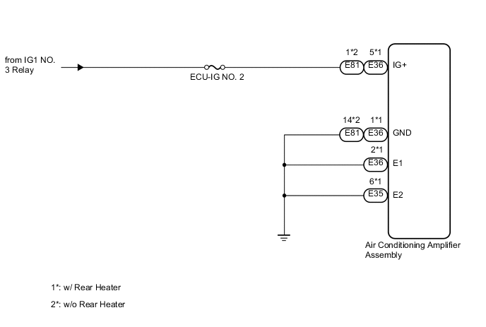
The main power source is supplied to the air conditioning amplifier assembly when the engine switch is on (IG). The power source is used for operating the air conditioning amplifier assembly and servo motor, etc.
WIRING DIAGRAM
CAUTION / NOTICE / HINT
Tech Tips
Start the engine before inspection. Check the relay or battery if the entry and start system does not start.
PROCEDURE
-
INSPECT FUSE (ECU-IG NO. 2)
-
Remove the ECU-IG NO. 2 fuse from the cowl side junction block LH.
-
Measure the resistance according to the value(s) in the table below.
Standard Resistance Tester Connection Condition Specified Condition ECU-IG NO. 2 fuse Always Below 1 Ω
NG 
REPLACE FUSE
OK 
-
-
CHECK HARNESS AND CONNECTOR (AIR CONDITIONING AMPLIFIER - BATTERY AND BODY GROUND)
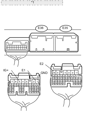
*1 Rear view of wire harness connector: (to Air Conditioning Amplifier Assembly)
-
w/ Rear Heater
-
Disconnect the E35 and E36 amplifier connectors.
-
Measure the voltage according to the value(s) in the table below.
Standard Voltage Tester Connection Switch Condition Specified Condition E36-5 (IG+) - Body ground Engine switch off Below 1 V Engine switch on (IG) 11 to 14 V -
Measure the resistance according to the value(s) in the table below.
Standard Resistance Tester Connection Condition Specified Condition E36-1 (GND) - Body ground Always Below 1 Ω E36-2 (E1) - Body ground E35-6 (E2) - Body ground
-
-
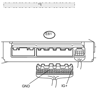
*1 Rear view of wire harness connector: (to Air Conditioning Amplifier Assembly) w/o Rear Heater
-
Disconnect the E81 amplifier connector.
-
Measure the voltage according to the value(s) in the table below.
Standard Voltage Tester Connection Switch Condition Specified Condition E81-1 (IG+) - Body ground Engine switch off Below 1 V Engine switch on (IG) 11 to 14 V -
Measure the resistance according to the value(s) in the table below.
Standard Resistance Tester Connection Condition Specified Condition E81-14 (GND) - Body ground Always Below 1 Ω
-
OK
REPLACE AIR CONDITIONING AMPLIFIER ASSEMBLY Click here
NG
REPAIR OR REPLACE HARNESS OR CONNECTOR
-