AIR CONDITIONING SYSTEM(for Automatic Air Conditioning System) Cooling Box Control Switch Circuit
DESCRIPTION
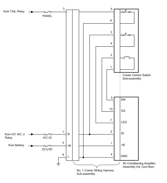
The cooler control switch is the activation switch for the cooling box. If the cooling box does not activate when the cooler control switch is pushed, there may be a malfunction in the circuit shown below.
WIRING DIAGRAM
PROCEDURE
-
INSPECT FUSE (PANEL, A/C IG, ECU-B1)
-
Remove the PANEL and A/C IG fuses from the cowl side junction block LH.
-
Remove the ECU-B1 fuse from the engine room relay block.
-
Measure the resistance according to the value(s) in the table below.
Standard Resistance Tester Connection Condition Specified Condition PANEL fuse Always Below 1 Ω ECU-B1 fuse Always Below 1 Ω A/C IG fuse Always Below 1 Ω
NG 
REPLACE FUSE
OK 
-
-
CHECK HARNESS AND CONNECTOR (NO. 1 COOLER WIRING HARNESS - BATTERY)
-
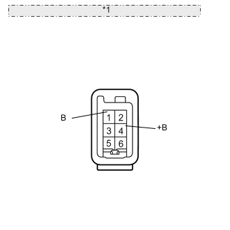
*1 Front view of wire harness connector: (to No. 1 Cooler Wiring Harness Sub-assembly) Disconnect the No. 1 cooler wiring harness sub-assembly connector.
-
Measure the voltage according to the value(s) in the table below.
Standard Voltage Tester Connection Condition Specified Condition 4 (+B) - Body ground Always 11 to 14 V 1 (B) - Body ground Engine switch off Below 1 V Engine switch on (IG) 11 to 14 V
NG
REPAIR OR REPLACE HARNESS OR CONNECTOR
OK
-
-
CHECK HARNESS AND CONNECTOR (NO. 1 COOLER WIRING HARNESS - BODY GROUND)
-
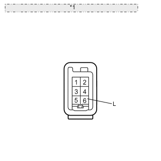
*1 Front view of wire harness connector: (to No. 1 Cooler Wiring Harness Sub-assembly) Disconnect the No. 1 cooler wiring harness sub-assembly connector.
-
Measure the resistance according to the value(s) in the table below.
Standard Resistance Tester Connection Condition Specified Condition 6 (L) - Body ground Always Below 1 Ω
NG
REPAIR OR REPLACE HARNESS OR CONNECTOR
OK
-
-
CHECK NO. 1 COOLER WIRING HARNESS SUB-ASSEMBLY (OPERATION)
-
Replace the No. 1 cooler wiring harness sub-assembly with a normal one and check that the condition returns to normal.
OK Same problem does not occur.
OK
REPLACE NO. 1 COOLER WIRING HARNESS SUB-ASSEMBLY
NG
-
-
INSPECT COOLER CONTROL SWITCH SUB-ASSEMBLY
-
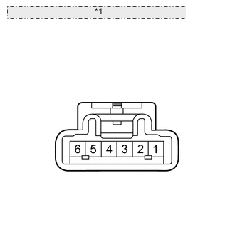
*1 Component with harness connected: (Cooler Control Switch Sub-assembly) Remove the cooler control switch sub-assembly Click here.
-
Measure the resistance according to the value(s) in the table below.
Standard Resistance Tester Connection Switch Condition Specified Condition 1 - 2 On Below 1 Ω 1 - 2 Off 10 kΩ or higher -
Apply battery voltage to the cooler control switch connector and check that the cooler control switch illuminates.
OK Measurement Condition Specified Condition Battery positive (+) → Terminal 3
Battery negative (-) → Terminal 4
LED illuminates Battery positive (+) → Terminal 5
Battery negative (-) → Terminal 6
LED illuminates
OK
REPLACE AIR CONDITIONING AMPLIFIER ASSEMBLY (for Cool Box) Click here
NG
REPLACE COOLER CONTROL SWITCH SUB-ASSEMBLY Click here
-