AIR CONDITIONING SYSTEM(for Automatic Air Conditioning System) Air Conditioning Control Panel does not Operate
DESCRIPTION
This circuit* consists of the air conditioning control assembly and the air conditioning amplifier assembly. When the air conditioning control assembly is operated, signals are transmitted to the air conditioning amplifier assembly through the LIN communication system.
If the LIN communication system malfunctions, the air conditioning amplifier assembly does not operate even if the air conditioning control assembly is operated.
Tech Tips
*: w/o Multi-display
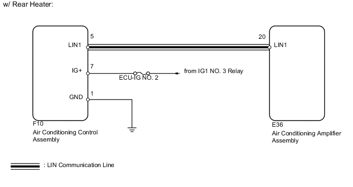
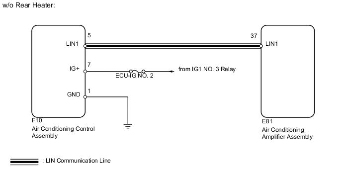
WIRING DIAGRAM
PROCEDURE
-
INSPECT FUSE (ECU-IG NO. 2)
-
Remove the ECU-IG NO. 2 fuse from the engine room relay block.
-
Measure the resistance according to the value(s) in the table below.
Standard Resistance Tester Connection Condition Specified Condition ECU-IG NO. 2 fuse Always Below 1 Ω
NG 
REPLACE FUSE
OK 
-
-
CHECK HARNESS AND CONNECTOR (AIR CONDITIONING CONTROL - BODY GROUND AND BATTERY)
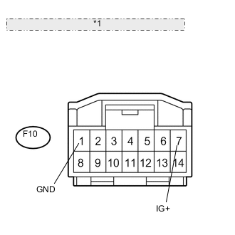
*1 Front view of wire harness connector: (to Air Conditioning Control Assembly)
-
Disconnect the F10 air conditioning control assembly connector.
-
Measure the resistance and voltage according to the value(s) in the table below.
Standard Resistance Tester Connection Condition Specified Condition F10-1 (GND) - Body ground Always Below 1 Ω Standard Voltage Tester Connection Switch Condition Specified Condition F10-1 (GND) - F10-7 (IG+) Engine switch on (IG) 11 to 14 V
NG
REPAIR OR REPLACE HARNESS OR CONNECTOR
OK
-
-
CHECK HARNESS AND CONNECTOR (AIR CONDITIONING AMPLIFIER - AIR CONDITIONING CONTROL)
-
w/ Rear Heater
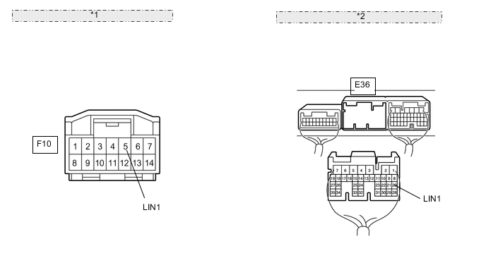
*1 Front view of wire harness connector: (to Air Conditioning Control Assembly) *2 Rear view of wire harness connector: (to Air Conditioning Amplifier Assembly)
-
Disconnect the F10 air conditioning control assembly connector.
-
Disconnect the E36 amplifier connector.
-
Measure the resistance according to the value(s) in the table below.
Standard Resistance Tester Connection Condition Specified Condition E36-20 (LIN1) - F10-5 (LIN1) Always Below 1 Ω E36-20 (LIN1) - Body ground Always 10 kΩ or higher
-
-
w/o Rear Heater
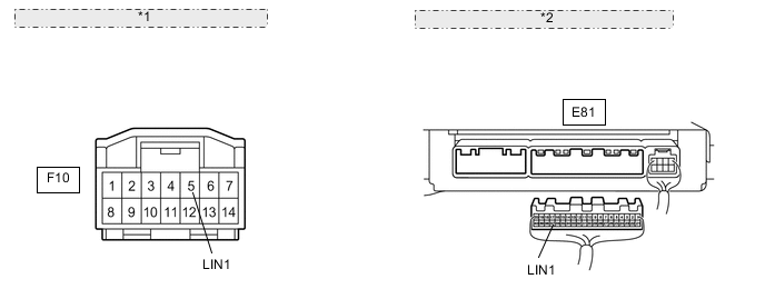
*1 Front view of wire harness connector: (to Air Conditioning Control Assembly) *2 Rear view of wire harness connector: (to Air Conditioning Amplifier Assembly)
-
Disconnect the F10 air conditioning control assembly connector.
-
Disconnect the E81 amplifier connector.
-
Measure the resistance according to the value(s) in the table below.
Standard Resistance Tester Connection Condition Specified Condition E81-37 (LIN1) - F10-5 (LIN1) Always Below 1 Ω E81-37 (LIN1) - Body ground Always 10 kΩ or higher
-
NG
REPAIR OR REPLACE HARNESS OR CONNECTOR
OK
-
-
CHECK AIR CONDITIONING CONTROL ASSEMBLY (OPERATION)
-
Replace the air conditioning control assembly with a new or properly functioning one.
-
Operate the front air conditioning control to check that it functions properly.
OK Air conditioning control assembly function operates normally.
OK
REPLACE AIR CONDITIONING CONTROL ASSEMBLY Click here
NG
REPLACE AIR CONDITIONING AMPLIFIER ASSEMBLY Click here
-