| DTC Code | DTC Name |
|---|---|
| B14B2 | Lost Communication with Front Panel LIN |
DESCRIPTION
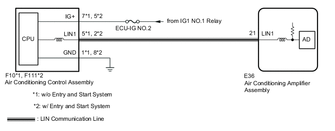
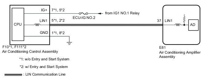
The air conditioning control assembly communicates with the air conditioning amplifier assembly through the LIN communication system.
If the LIN communication system malfunctions, the air conditioning amplifier assembly does not operate even if the air conditioning control assembly is operated.
| DTC No. | DTC Detection Condition | Trouble Area |
|---|---|---|
| B14B2 | Lost communication with the air conditioning control assembly |
|
PROCEDURE
- Click here
CHECK HARNESS AND CONNECTOR (AIR CONDITIONING CONTROL ASSEMBLY - BATTERY AND BODY GROUND)
-
Disconnect the F10*1 or F111*2 air conditioning control assembly connector.
-
*1: w/o Entry and Start System
-
*2: w/ Entry and Start System
-
-
Measure the resistance according to value(s) in the table below.
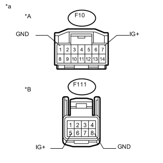
Standard Resistance w/o Entry and Start System Tester Connection Condition Specified Condition F10-1 (GND) - Body ground Always Below 1 Ω w/ Entry and Start System Tester Connection Condition Specified Condition F111-8 (GND) - Body ground Always Below 1 Ω -
Measure the voltage according to value(s) in the table below.
Standard Voltage w/o Entry and Start System Tester Connection Condition Specified Condition F10-7 (IG+) - Body ground Ignition switch off Below 1 V Ignition switch ON 11 to 14 V w/o Entry and Start System Tester Connection Condition Specified Condition F111-5 (IG+) - Body ground Ignition switch off Below 1 V Ignition switch ON 11 to 14 V Table 1. Text in Illustration *A w/o Entry and Start System *B w/ Entry and Start System *a Front view of wire harness connector
(to Air Conditioning Control Assembly)
- OKClick here
- NG
REPAIR OR REPLACE HARNESS OR CONNECTOR
-
- Click here
CHECK HARNESS AND CONNECTOR (AIR CONDITIONING CONTROL ASSEMBLY - AIR CONDITIONING AMPLIFIER ASSEMBLY)
-
w/ Rear Heater:
-
Disconnect the F10*1 or F111*2 air conditioning control assembly connector.
-
*1: w/o Entry and Start System
-
*2: w/ Entry and Start System
-
-
Disconnect the E36 air conditioning amplifier assembly connector.
-
Measure the resistance according to the value(s) in the table below.
Standard Resistance w/o Entry and Start System Tester Connection Condition Specified Condition F10-5 (LIN1) - E36-21 (LIN1) Always Below 1 Ω F10-5 (LIN1) or E36-21 (LIN1) - Body ground Always 10 kΩ or higher w/ Entry and Start System Tester Connection Condition Specified Condition F111-2 (LIN1) - E36-21 (LIN1) Always Below 1 Ω F111-2 (LIN1) or E36-21 (LIN1) - Body ground Always 10 kΩ or higher
-
-
w/o Rear Heater:
-
Disconnect the F10*1 or F111*2 air conditioning control assembly connector.
-
*1: w/o Entry and Start System
-
*2: w/ Entry and Start System
-
-
Disconnect the E81 air conditioning amplifier assembly connector.
-
Measure the resistance according to the value(s) in the table below.
Standard Resistance w/o Entry and Start System Tester Connection Condition Specified Condition F10-5 (LIN1) - E81-37 (LIN1) Always Below 1 Ω F10-5 (LIN1) or E81-37 (LIN1) - Body ground Always 10 kΩ or higher w/ Entry and Start System Tester Connection Condition Specified Condition F111-2 (LIN1) - E81-37 (LIN1) Always Below 1 Ω F111-2 (LIN1) or E81-37 (LIN1) - Body ground Always 10 kΩ or higher
-
- OKClick here
- NG
REPAIR OR REPLACE HARNESS OR CONNECTOR
-
- Click here
CHECK AIR CONDITIONING CONTROL ASSEMBLY
-
Replace the air conditioning control assembly with a new or known good one.
-
w/ Entry and Start System:Click here
-
w/o Entry and Start System:Click here
-
-
When troubleshooting according to the DTC:
-
Clear the DTCs (Click here).
-
Check for DTCs (Click here).
OK DTC B14B2 is not output.
-
-
When troubleshooting according to Problem Symptoms Table:
-
Check the air conditioning control assembly operates normally.
Tip:Since the air conditioning control assembly cannot be inspected while it is removed from the vehicle, replace the air conditioning control assembly with a new or known good one and check that the condition returns to normal.
OK Air conditioning control assembly operation returns to normal.
-
- A
END (AIR CONDITIONING CONTROL ASSEMBLY WAS DEFECTIVE)
- B
REPLACE AIR CONDITIONING AMPLIFIER ASSEMBLY (Click here)
- C
PROCEED TO NEXT SUSPECTED AREA SHOWN IN PROBLEM SYMPTOMS TABLE (Click here)
-