AIR CONDITIONING SYSTEM(for Automatic Air Conditioning System), Diagnostic DTC:B1467/67
| DTC Code | DTC Name |
|---|---|
| B1467/67 | Rear Air Foot Duct Sensor Circuit on Driver Side |
DESCRIPTION
-
*1: for LHD
-
*2: for RHD
The cooler thermistor (duct sensor LH*1 or RH*2) detects the duct temperature and sends the appropriate signals to the air conditioning amplifier assembly.
| DTC Code | DTC Detection Condition | Trouble Area |
|---|---|---|
| B1467/67 | An open or short in the air duct temperature sensor LH*1 or RH*2 circuit. |
|
WIRING DIAGRAM
-
for LHD:
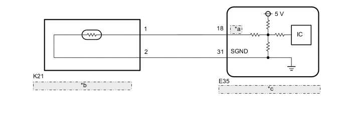
*a RHTL *b Cooler Thermistor (Duct Sensor LH) *c Air Conditioning Amplifier Assembly -
for RHD:
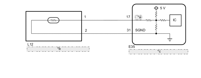
*a RHTR *b Cooler Thermistor (Duct Sensor RH) *c Air Conditioning Amplifier Assembly
PROCEDURE
-
READ VALUE USING GTS (FOOT DUCT SENSOR [REAR D])
-
*1: for LHD
-
*2: for RHD
-
Use the Data List to check if the cooler thermistor (duct sensor LH*1 or RH*2) is functioning properly Click here.
Air Conditioner Tester Display Measurement Item/Range Normal Condition Diagnostic Note Foot Duct Sensor (Rear D) Cooler thermistor (duct sensor LH*1 or RH*2) / Min.: -12.7°C (9.14°F), Max.: 76.55°C (169.79°F) Cooler thermistor (duct sensor LH*1 or RH*2) displayed Cooler thermistor (duct sensor LH*1 or RH*2) system malfunction:
-
Open in the circuit: -12.7°C (9.14°F)
-
Short in the circuit: 76.55°C (169.79°F)
OK The display is as specified in the normal condition. -
OK 
REPLACE AIR CONDITIONING AMPLIFIER ASSEMBLY Click here
NG 
-
-
CHECK COOLER THERMISTOR (DUCT SENSOR [for Driver Side])
-
Remove the cooler thermistor (duct sensor LH*1 or RH*2) Click here.
-
Inspect the cooler thermistor (duct sensor LH*1 or RH*2) Click here
NG
REPLACE COOLER THERMISTOR (DUCT SENSOR) (for Driver Side) Click here
OK
-
-
CHECK HARNESS AND CONNECTOR (COOLER THERMISTOR [DUCT SENSOR] - AIR CONDITIONING AMPLIFIER ASSEMBLY)
-
for LHD:
-
Disconnect the K21 cooler thermistor (duct sensor LH) connector.
-
Disconnect the E35 air conditioning amplifier assembly connector.
-
Measure the resistance according to the value(s) in the table below.
Standard Resistance Tester Connection Condition Specified Condition E35-18 (RHTL) - K21-1 Always Below 1 Ω E35-31 (SGND) - K21-2 Always Below 1 Ω E35-18 (RHTL) - E35-31 (SGND) Always 10 kΩ or higher E35-18 (RHTL) or K21-1 - Body ground Always 10 kΩ or higher E35-31 (SGND) or K21-2 - Body ground Always 10 kΩ or higher
-
-
for RHD:
-
Disconnect the L12 cooler thermistor (duct sensor RH) connector.
-
Disconnect the E35 air conditioning amplifier assembly connector.
-
Measure the resistance according to the value(s) in the table below.
Standard Resistance Tester Connection Condition Specified Condition E35-17 (RHTR) - L12-1 Always Below 1 Ω E35-31 (SGND) - L12-2 Always Below 1 Ω E35-17 (RHTR) - E35-31 (SGND) Always 10 kΩ or higher E35-17 (RHTR) or L12-1 - Body ground Always 10 kΩ or higher E35-31 (SGND) or L12-2 - Body ground Always 10 kΩ or higher
-
OK
REPLACE AIR CONDITIONING AMPLIFIER ASSEMBLY Click here
NG
REPAIR OR REPLACE HARNESS OR CONNECTOR
-