AIR CONDITIONING SYSTEM(for Automatic Air Conditioning System), Diagnostic DTC:B1467/67
| DTC Code | DTC Name |
|---|---|
| B1467/67 | Rear Air Foot Duct Sensor Circuit on Driver Side |
DESCRIPTION
The air duct temperature sensor LH*1 or RH*2 (for driver side) detects the duct temperature and sends the appropriate signals to the air conditioning amplifier assembly.
| DTC Code | DTC Detection Condition | Trouble Area |
|---|---|---|
| B1467/67 | An open or short in the air duct temperature sensor LH*1 or RH*2 circuit. |
|
Tech Tips
*1: for LHD
*2: for RHD
WIRING DIAGRAM
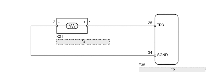
| *a | Air Duct Temperature Sensor LH |
| *b | Air Conditioning Amplifier Assembly |
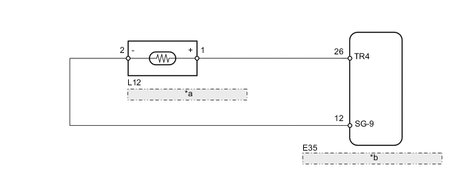
| *a | Air Duct Temperature Sensor RH |
| *b | Air Conditioning Amplifier Assembly |
PROCEDURE
-
READ VALUE USING INTELLIGENT TESTER (AIR DUCT TEMPERATURE SENSOR)
-
Use the Data List to check if the air duct temperature sensor LH*1 or RH*2 (for driver side) is functioning properly.
Air Conditioner Tester Display Measurement Item/Range Normal Condition Diagnostic Note Foot Duct Sensor (Rear D) Min.: -12.7°C (9.14°F)
Max.: 76.55°C (169.79°F)
Actual air duct temperature sensor (for driver side) displayed Open in the circuit: -12.7°C (9.14°F)
Short in the circuit: 76.55°C (169.79°F)
Tech Tips
*1: for LHD
*2: for RHD
OK The display is as specified in the normal condition.
OK 
REPLACE AIR CONDITIONING AMPLIFIER ASSEMBLY Click here
NG 
-
-
CHECK AIR DUCT TEMPERATURE SENSOR
-
for LHD
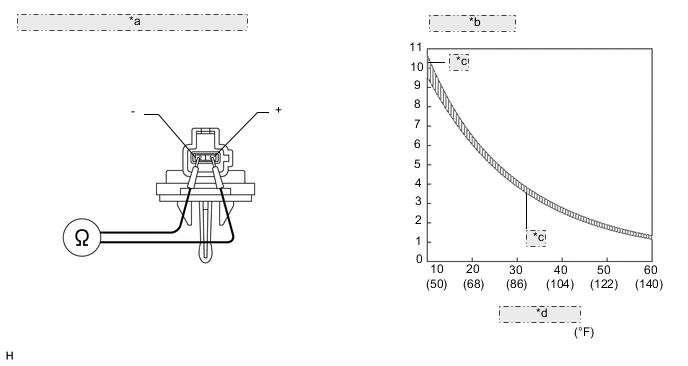
*a Component without harness connected: (Air Duct Temperature Sensor) *b Resistance (kΩ) *c Maximum per missible value line *d Temperature °C
-
Remove the air duct temperature sensor LH Click here.
-
-
for RHD
-
Remove the air duct temperature sensor RH Click here.
-
-
Measure the resistance according to the value(s) in the table below.
Standard Resistance Tester Connection Condition Specified Condition 1 (+) - 2 (-) at 10°C (50°F) 9.4 to 10.5 kΩ at 15°C (59°F) 7.5 to 8.3 kΩ at 20°C (68°F) 6.0 to 6.5 kΩ at 25°C (77°F) 4.5 to 5.2 kΩ at 30°C (86°F) 3.8 to 4.2 kΩ at 35°C (95°F) 3.1 to 3.4 kΩ at 40°C (104°F) 2.5 to 2.8 kΩ at 45°C (113°F) 2.0 to 2.3 kΩ at 50°C (122°F) 1.6 to 2.0 kΩ at 55°C (131°F) 1.3 to 1.6 kΩ at 60°C (140°F) 1.1 to 1.4 kΩ Note
-
Touching the sensor even slightly may change the resistance value. Hold the connector of the sensor.
-
When measuring the resistance, the sensor temperature must be the same as the ambient temperature.
Tech Tips
As the temperature increases, the resistance decreases (see the graph).
If the resistance value is not as specified, replace the sensor.
Result Result Proceed to OK A NG (for LHD) B NG (for RHD) C -
B
REPLACE AIR DUCT TEMPERATURE SENSOR LH Click here
C
REPLACE AIR DUCT TEMPERATURE SENSOR RH Click here
A
-
-
CHECK HARNESS AND CONNECTOR (AIR CONDITIONING AMPLIFIER - AIR DUCT TEMPERATURE SENSOR)
-
for LHD
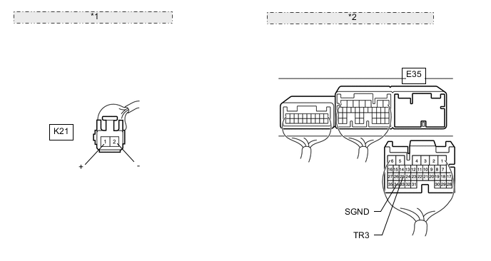
*1 Front view of wire harness connector: (to Air Duct Temperature Sensor LH) *2 Rear view of wire harness connector: (to Air Conditioning Amplifier Assembly)
-
Disconnect the K21 sensor connector.
-
Disconnect the E35 amplifier connector.
-
Measure the resistance according to the value(s) in the table below.
Standard Resistance Tester Connection Condition Specified Condition E35-25 (TR3) - K21-1 (+) Always Below 1 Ω E35-34 (SGND) - K21-2 (-) E35-25 (TR3) - Body ground Always 10 kΩ or higher E35-34 (SGND) - Body ground
-
-
for RHD
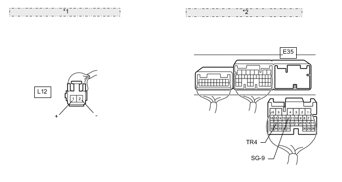
*1 Front view of wire harness connector: (to Air Duct Temperature Sensor RH) *2 Rear view of wire harness connector: (to Air Conditioning Amplifier Assembly)
-
Disconnect the L12 sensor connector.
-
Disconnect the E35 amplifier connector.
-
Measure the resistance according to the value(s) in the table below.
Standard Resistance Tester Connection Condition Specified Condition E35-26 (TR4) - L12-1 (+) Always Below 1 Ω E35-12 (SG-9) - L12-2 (-) E35-26 (TR4) - Body ground Always 10 kΩ or higher E35-12 (SG-9) - Body ground
-
OK
REPLACE AIR CONDITIONING AMPLIFIER ASSEMBLY Click here
NG
REPAIR OR REPLACE HARNESS OR CONNECTOR
-