AIR CONDITIONING SYSTEM(for Automatic Air Conditioning System), Diagnostic DTC:B1449/49
| DTC Code | DTC Name |
|---|---|
| B1449/49 | Rear Air Outlet Damper Control Servo Motor Circuit |
DESCRIPTION
The rear mode damper servo motor sends pulse signals to inform the air conditioning amplifier assembly of the damper position. The air conditioning amplifier assembly activates the motor (normal or reverse) based on the signals to move the rear mode damper servo motor to the appropriate position, which controls the air outlet modes.
Tech Tips
Confirm that no mechanical problem is present because this trouble code can be output when either a damper link or damper is mechanically locked.
| DTC Code | DTC Detection Condition | Trouble Area |
|---|---|---|
| B1449/49 | The rear mode damper servo motor position does not change even if the air conditioning amplifier assembly operates the rear air outlet damper servo motor. |
|
WIRING DIAGRAM
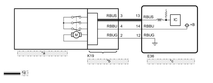
| *a | Rear Mode Damper Servo Motor |
| *b | No. 2 Air Conditioning Harness Assembly |
| *c | Air Conditioning Amplifier Assembly |
| *d | LIN Communication Line |
PROCEDURE
-
READ VALUE USING GTS (AIR OUTLET SERVO [R], AIR OUTLET SERVO ACTUAL PLS[R])
-
Use the Data List to check if the rear mode damper servo motor is functioning properly Click here.
Air Conditioner Tester Display Measurement Item/Range Normal Condition Diagnostic Note Air Outlet Servo Pulse (R) Rear mode damper servo motor target pulse / Min.: 128, Max.: 383
-
FACE1: 258 (pulse)
-
FACE2: 258 (pulse)
-
B/L1: 277 (pulse)
-
FOOT-O: 290 (pulse)
-
FOOT-D: 290 (pulse)
-
FOOT-R: 290 (pulse)
-
FOOT-M: 307 (pulse)
-
F/D: 316 (pulse)
-
DEF: 328 (pulse)
-
Displayed between 258 and 328 pulse
-
Rear mode damper servo motor system malfunction
Air Outlet Servo Actual Pls(R) Rear mode damper servo motor actual pulse / Min.: 128, Max.: 383
-
FACE1: 258 (pulse)
-
FACE2: 258 (pulse)
-
B/L1: 277 (pulse)
-
FOOT-O: 290 (pulse)
-
FOOT-D: 290 (pulse)
-
FOOT-R: 290 (pulse)
-
FOOT-M: 307 (pulse)
-
F/D: 316 (pulse)
-
DEF: 328 (pulse)
-
Displayed between 258 and 328 pulse
-
Rear mode damper servo motor system malfunction
OK When the rear mode switch is turned, the actual pulse changes following the target pulse. Result Result Proceed to Target pulse changes but actual pulse does not change A Target pulse and actual pulse do not change B Actual pulse changes following the target pulse (When troubleshooting according to the DTC) C Actual pulse changes following the target pulse (When troubleshooting according to Problem Symptoms Table) D -
B 
REPLACE AIR CONDITIONING AMPLIFIER ASSEMBLY Click here
C 
CHECK FOR DTC Click here
E
PROCEED TO NEXT SUSPECTED AREA SHOWN IN PROBLEM SYMPTOMS TABLE Click here
A 
-
-
CHECK HARNESS AND CONNECTOR (NO. 2 AIR CONDITIONING HARNESS ASSEMBLY - AIR CONDITIONING AMPLIFIER ASSEMBLY)
-
Disconnect the K19 No. 2 air conditioning harness assembly connector.
-
Disconnect the E36 air conditioning amplifier assembly connector.
-
Measure the resistance according to the value(s) in the table below.
Standard Resistance Tester Connection Condition Specified Condition K19-2 (RBUG) - E36-12 (RBUG) Always Below 1 Ω K19-3 (RBUS) - E36-13 (RBUS) Always Below 1 Ω K19-4 (RBBU) - E36-14 (RBBU) Always Below 1 Ω K19-2 (RBUG) or E36-12 (RBUG) - Body ground Always 10 kΩ or higher K19-3 (RBUS) or E36-13 (RBUS) - Body ground Always 10 kΩ or higher K19-4 (RBBU) or E36-14 (RBBU) - Body ground Always 10 kΩ or higher
NG
REPAIR OR REPLACE HARNESS OR CONNECTOR
OK
-
-
CHECK REAR MODE DAMPER SERVO MOTOR
-
Replace the rear mode damper servo motor Click here.
Tech Tips
Since the servo motor cannot be inspected while it is removed from the vehicle, replace the servo motor with a normal one.
-
Clear the DTCs Click here.
-
Check for DTCs Click here.
OK DTC B1449/49 is not output.
OK
END (REAR MODE DAMPER SERVO MOTOR WAS DEFECTIVE)
NG
-
-
CHECK NO. 2 AIR CONDITIONING HARNESS ASSEMBLY
-
Replace the No. 2 air conditioning harness assembly with a new or known good one Click here.
-
Clear the DTCs Click here.
-
Check for DTCs Click here.
OK DTC B1449/49 is not output.
OK
END (NO. 2 AIR CONDITIONING HARNESS ASSEMBLY WAS DEFECTIVE)
NG
REPLACE AIR CONDITIONING AMPLIFIER ASSEMBLY Click here
-
-
CHECK FOR DTC
-
Clear the DTCs Click here.
-
Check for DTCs Click here.
OK DTC B1449/49 is not output.
OK
USE SIMULATION METHOD TO CHECK Click here
NG
REPLACE AIR CONDITIONING AMPLIFIER ASSEMBLY Click here
-