AIR CONDITIONING SYSTEM(for Automatic Air Conditioning System) Air Conditioning Compressor Magnetic Clutch Circuit
DESCRIPTION
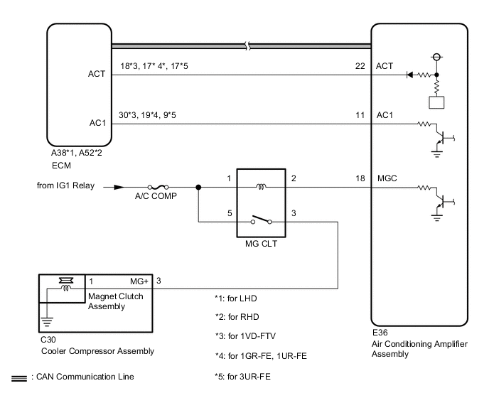
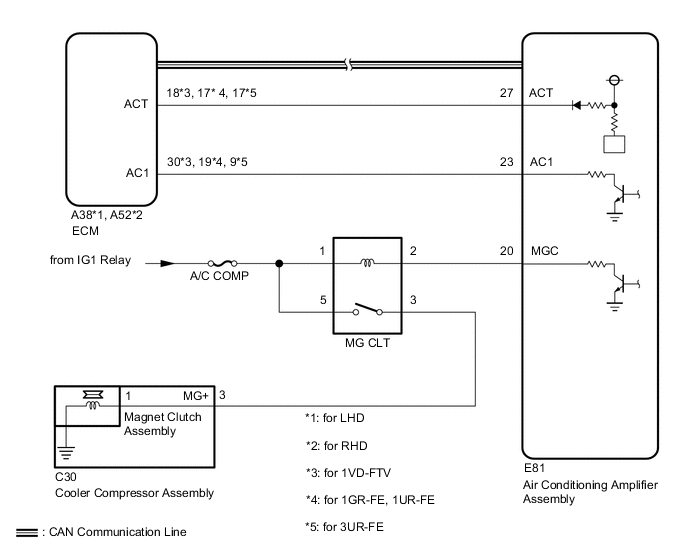
When the air conditioning amplifier assembly is turned on, a magnet clutch assembly on signal is sent from the MGC terminal of the air conditioning amplifier assembly. Then, the magnet clutch relay turns on to operate the magnet clutch assembly.
WIRING DIAGRAM
-
w/ Rear Heater:
-
w/o Rear Heater:
CAUTION / NOTICE / HINT
Note
-
Inspect the fuses for circuits related to this system before performing the following inspection procedure.
-
Since the air conditioning system has functions that use CAN communication system, first confirm that there is no malfunction in the communication system by inspecting the CAN communication functions in accordance with the "How to Proceed with Troubleshooting" procedures. Then, conduct the following inspection procedure Click here.
PROCEDURE
-
READ VALUE USING GTS (A/C SWITCH SIGNAL)
-
Use the Data List to check if the A/C switch is functioning properly Click here.
Engine Tester Display Measurement Item/Range Normal Condition Diagnostic Note A/C Signal A/C switch signal / ON or OFF ON: A/C switch on
OFF: A/C switch off
- OK The display is as specified in the normal condition.
NG 
CHECK HARNESS AND CONNECTOR (ECM - AIR CONDITIONING AMPLIFIER ASSEMBLY) Click here
OK 
-
-
INSPECT MAGNET CLUTCH RELAY (MG CLT)
-
Remove the MG CLT relay from the No. 1 engine room relay block.
-
Inspect the MG CLT relay Click here.
NG 
REPLACE MAGNET CLUTCH RELAY Click here
OK
-
-
CHECK HARNESS AND CONNECTOR (AIR CONDITIONING AMPLIFIER ASSEMBLY - BATTERY)
-
w/ Rear Heater:
-
Disconnect the air conditioning amplifier assembly connector.
-
Measure the voltage according to the value(s) in the table below.
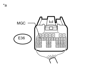
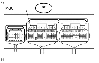
Standard Voltage Tester Connection Switch Condition Specified Condition E36-18 (MGC) - Body ground Ignition switch off Below 1 V E36-18 (MGC) - Body ground Ignition switch ON 11 to 14 V
-
-
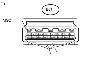
Text in Illustration *a Rear view of wire harness connector
(to Air Conditioning Amplifier Assembly)
w/o Rear Heater:
-
Disconnect the air conditioning amplifier assembly connector.
-
Measure the voltage according to the value(s) in the table below.
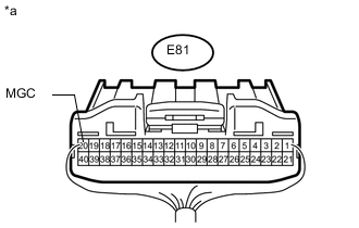
Standard Voltage Tester Connection Switch Condition Specified Condition E81-20 (MGC) - Body ground Ignition switch off Below 1 V E81-20 (MGC) - Body ground Ignition switch ON 11 to 14 V
-
NG
REPAIR OR REPLACE HARNESS OR CONNECTOR
OK
-
-
CHECK AIR CONDITIONING AMPLIFIER ASSEMBLY
-
w/ Rear Heater:
-
Reconnect the air conditioning amplifier assembly connector.
-
Measure the voltage according to the value(s) in the table below.
Standard Voltage Tester Connection Switch Condition Specified Condition E36-18 (MGC) - Body ground
-
Engine idling
-
A/C switch off
-
Blower switch LO
11 to 14 V E36-18 (MGC) - Body ground
-
Engine idling
-
A/C switch on
-
Blower switch LO
Below 1 V -
-
-
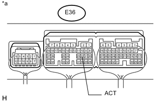
Text in Illustration *a Component with harness connected
(Air Conditioning Amplifier Assembly)
w/ Rear Heater:
-
Reconnect the air conditioning amplifier assembly connector.
-
Measure the voltage according to the value(s) in the table below.
Standard Voltage Tester Connection Switch Condition Specified Condition E81-20 (MGC) - Body ground
-
Engine idling
-
A/C switch off
-
Blower switch LO
11 to 14 V E81-20 (MGC) - Body ground
-
Engine idling
-
A/C switch on
-
Blower switch LO
Below 1 V -
-
NG
CHECK HARNESS AND CONNECTOR (ECM - AIR CONDITIONING AMPLIFIER ASSEMBLY) Click here
OK
-
-
CHECK COOLER COMPRESSOR ASSEMBLY
-
Disconnect the C30 cooler compressor assembly connector.
-
Disconnect the magnet clutch assembly connector.
-
Measure the resistance according to the value(s) in the table below.
Standard Resistance Tester Connection Condition Specified Condition C30-3 (MG+) - 1 Always Below 1 Ω C30-3 (MG+) or 1 -Body ground Always 10 kΩ or higher Result Result Proceed to OK A NG (for 1VD-FTV) B NG (for 1GR-FE) C NG (for 1UR-FE) D NG (for 3UR-FE) E
B
REPLACE COOLER COMPRESSOR ASSEMBLY Click here
C
REPLACE COOLER COMPRESSOR ASSEMBLY Click here
D
REPLACE COOLER COMPRESSOR ASSEMBLY Click here
E
REPLACE COOLER COMPRESSOR ASSEMBLY Click here
A
-
-
INSPECT MAGNET CLUTCH ASSEMBLY
-
Remove the magnet clutch assembly.
-
for 1VD-FTV: Click here
-
for 1GR-FE: Click here
-
for 1UR-FE: Click here
-
for 3UR-FE: Click here
-
-
Inspect the magnet clutch assembly.
-
for 1VD-FTV: Click here
-
for 1GR-FE: Click here
-
for 1UR-FE: Click here
-
for 3UR-FE: Click here
Result Result Proceed to OK A NG (for 1VD-FTV) B NG (for 1GR-FE) C NG (for 1UR-FE) D NG (for 3UR-FE) E -
B
REPLACE MAGNET CLUTCH ASSEMBLY Click here
C
REPLACE MAGNET CLUTCH ASSEMBLY Click here
D
REPLACE MAGNET CLUTCH ASSEMBLY Click here
E
REPLACE MAGNET CLUTCH ASSEMBLY Click here
A
-
-
CHECK HARNESS AND CONNECTOR (MAGNET CLUTCH RELAY - BATTERY)
-
Remove the MG CLT relay from the No. 1 engine room relay block.
-
Measure the voltage according to the value(s) in the table below.
Standard Voltage Tester Connection Switch Condition Specified Condition Relay block MG CLT relay terminal 5 - Body ground Ignition switch ON 11 to 14 V Relay block MG CLT relay terminal 1 - Body ground Ignition switch ON 11 to 14 V
OK
PROCEED TO NEXT CIRCUIT INSPECTION SHOWN IN PROBLEM SYMPTOMS TABLE Click here
NG
REPAIR OR REPLACE HARNESS OR CONNECTOR
-
-
CHECK HARNESS AND CONNECTOR (ECM - AIR CONDITIONING AMPLIFIER ASSEMBLY)
-
*1: for LHD
-
*2: for RHD
-
w/ Rear Heater:
-
Disconnect the A38*1 or A52*2 ECM connector.
-
Disconnect the E36 air conditioning amplifier assembly connector.
-
Measure the resistance according to the value(s) in the table below.
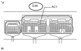
Standard Resistance for 1VD-FTV Tester Connection Condition Specified Condition A38-18 (ACT) - E36-22 (ACT)*1 Always Below 1 Ω A38-30 (AC1) - E36-11 (AC1)*1 Always Below 1 Ω A52-18 (ACT) - E36-22 (ACT)*2 Always Below 1 Ω A52-30 (AC1) - E36-11 (AC1)*2 Always Below 1 Ω A38-18 (ACT) or E36-22 (ACT) - Body ground*1 Always 10 kΩ or higher A38-30 (AC1) or E36-11 (AC1) - Body ground*1 Always 10 kΩ or higher A52-18 (ACT) or E36-22 (ACT) - Body ground*2 Always 10 kΩ or higher A52-30 (AC1) or E36-11 (AC1) - Body ground*2 Always 10 kΩ or higher for 1GR-FE, 1UR-FE Tester Connection Condition Specified Condition A38-17 (ACT) - E36-22 (ACT)*1 Always Below 1 Ω A38-19 (AC1) - E36-11 (AC1)*1 Always Below 1 Ω A52-17 (ACT) - E36-22 (ACT)*2 Always Below 1 Ω A52-19 (AC1) - E36-11 (AC1)*2 Always Below 1 Ω A38-17 (ACT) or E36-22 (ACT) - Body ground*1 Always 10 kΩ or higher A38-19 (AC1) or E36-11 (AC1) - Body ground*1 Always 10 kΩ or higher A52-17 (ACT) or E36-22 (ACT) - Body ground*2 Always 10 kΩ or higher A52-19 (AC1) or E36-11 (AC1) - Body ground*2 Always 10 kΩ or higher for 3UR-FE Tester Connection Condition Specified Condition A38-17 (ACT) - E36-22 (ACT) Always Below 1 Ω A38-9 (AC1) - E36-11 (AC1) Always Below 1 Ω A38-17 (ACT) or E36-22 (ACT) - Body ground Always 10 kΩ or higher A38-9 (AC1) or E36-11 (AC1) - Body ground Always 10 kΩ or higher
-
-
w/o Rear Heater:
-
Disconnect the A38*1 or A52*2 ECM connector.
-
Disconnect the E81 air conditioning amplifier assembly connector.
-
Measure the resistance according to the value(s) in the table below.
Standard Resistance for 1VD-FTV Tester Connection Condition Specified Condition A38-18 (ACT) - E81-27 (ACT)*1 Always Below 1 Ω A38-30 (AC1) - E81-23 (AC1)*1 Always Below 1 Ω A52-18 (ACT) - E81-27 (ACT)*2 Always Below 1 Ω A52-30 (AC1) - E81-23 (AC1)*2 Always Below 1 Ω A38-18 (ACT) or E81-27 (ACT) - Body ground*1 Always 10 kΩ or higher A38-30 (AC1) or E81-23 (AC1) - Body ground*1 Always 10 kΩ or higher A52-18 (ACT) or E81-27 (ACT) - Body ground*2 Always 10 kΩ or higher A52-30 (AC1) or E81-23 (AC1) - Body ground*2 Always 10 kΩ or higher for 1GR-FE, 1UR-FE Tester Connection Condition Specified Condition A38-17 (ACT) - E81-27 (ACT)*1 Always Below 1 Ω A38-19 (AC1) - E81-23 (AC1)*1 Always Below 1 Ω A52-17 (ACT) - E81-27 (ACT)*2 Always Below 1 Ω A52-19 (AC1) - E81-23 (AC1)*2 Always Below 1 Ω A38-17 (ACT) or E81-27 (ACT) - Body ground*1 Always 10 kΩ or higher A38-19 (AC1) or E81-23 (AC1) - Body ground*1 Always 10 kΩ or higher A52-17 (ACT) or E81-27 (ACT) - Body ground*2 Always 10 kΩ or higher A52-19 (AC1) or E81-23 (AC1) - Body ground*2 Always 10 kΩ or higher for 3UR-FE Tester Connection Condition Specified Condition A38-17 (ACT) - E81-27 (ACT) Always Below 1 Ω A38-9 (AC1) - E81-23 (AC1) Always Below 1 Ω A38-17 (ACT) or E81-27 (ACT) - Body ground Always 10 kΩ or higher A38-9 (AC1) or E81-23 (AC1) - Body ground Always 10 kΩ or higher
-
NG
REPAIR OR REPLACE HARNESS OR CONNECTOR
OK
-
-
CHECK AIR CONDITIONING AMPLIFIER ASSEMBLY
-
w/ Rear Heater:
-
Remove the air conditioning amplifier assembly with its connectors still connected Click here.
-
Measure the voltage according to the value(s) in the table below.
Standard Voltage Tester Connection Switch Condition Specified Condition E36-11 (AC1) - Body ground
-
Engine idling
-
A/C switch off
-
Blower switch LO
11 to 14 V E36-11 (AC1) - Body ground
-
Engine idling
-
A/C switch on
-
Blower switch LO
Below 1 V -
-
-
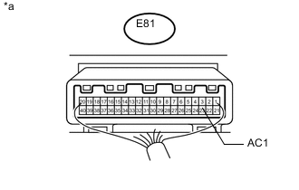
Text in Illustration *a Component with harness connected
(Air Conditioning Amplifier Assembly)
w/ Rear Heater:
-
Remove the air conditioning amplifier assembly with its connectors still connected Click here.
-
Measure the voltage according to the value(s) in the table below.
Standard Voltage Tester Connection Switch Condition Specified Condition E81-23 (AC1) - Body ground
-
Engine idling
-
A/C switch off
-
Blower switch LO
11 to 14 V E81-23 (AC1) - Body ground
-
Engine idling
-
A/C switch on
-
Blower switch LO
Below 1 V -
Result Result Proceed to OK A NG (for 1VD-FTV) B NG (for 1GR-FE) C NG (for 1UR-FE) D NG (for 3UR-FE) E -
A
REPLACE ECM Click here
B
REPLACE AIR CONDITIONING AMPLIFIER ASSEMBLY Click here
C
REPLACE ECM Click here
D
REPLACE ECM Click here
E
REPLACE ECM Click here
-
-
CHECK HARNESS AND CONNECTOR (ECM - AIR CONDITIONING AMPLIFIER ASSEMBLY)
-
*1: for LHD
-
*2: for RHD
-
w/ Rear Heater:
-
Disconnect the A38*1 or A52*2 ECM connector.
-
Disconnect the E36 air conditioning amplifier assembly connector.
-
Measure the resistance according to the value(s) in the table below.
Standard Resistance for 1VD-FTV Tester Connection Condition Specified Condition A38-18 (ACT) - E36-22 (ACT)*1 Always Below 1 Ω A52-18 (ACT) - E36-22 (ACT)*2 Always Below 1 Ω A38-18 (ACT) or E36-22 (ACT) - Body ground*1 Always 10 kΩ or higher A52-18 (ACT) or E36-22 (ACT) - Body ground*2 Always 10 kΩ or higher for 1GR-FE, 1UR-FE Tester Connection Condition Specified Condition A38-17 (ACT) - E36-22 (ACT)*1 Always Below 1 Ω A52-17 (ACT) - E36-22 (ACT)*2 Always Below 1 Ω A38-17 (ACT) or E36-22 (ACT) - Body ground*1 Always 10 kΩ or higher A52-17 (ACT) or E36-22 (ACT) - Body ground*2 Always 10 kΩ or higher for 3UR-FE Tester Connection Condition Specified Condition A38-17 (ACT) - E36-22 (ACT) Always Below 1 Ω A38-17 (ACT) or E36-22 (ACT) - Body ground Always 10 kΩ or higher
-
-
w/o Rear Heater:
-
Disconnect the A38*1 or A52*2 ECM connector.
-
Disconnect the E81 air conditioning amplifier assembly connector.
-
Measure the resistance according to the value(s) in the table below.
Standard Resistance for 1VD-FTV Tester Connection Condition Specified Condition A38-18 (ACT) - E81-27 (ACT)*1 Always Below 1 Ω A52-18 (ACT) - E81-27 (ACT)*2 Always Below 1 Ω A38-18 (ACT) or E81-27 (ACT) - Body ground*1 Always 10 kΩ or higher A52-18 (ACT) or E81-27 (ACT) - Body ground*2 Always 10 kΩ or higher for 1GR-FE, 1UR-FE Tester Connection Condition Specified Condition A38-17 (ACT) - E81-27 (ACT)*1 Always Below 1 Ω A52-17 (ACT) - E81-27 (ACT)*2 Always Below 1 Ω A38-17 (ACT) or E81-27 (ACT) - Body ground*1 Always 10 kΩ or higher A52-17 (ACT) or E81-27 (ACT) - Body ground*2 Always 10 kΩ or higher for 3UR-FE Tester Connection Condition Specified Condition A38-17 (ACT) - E81-27 (ACT) Always Below 1 Ω A38-17 (ACT) or E81-27 (ACT) - Body ground Always 10 kΩ or higher
-
NG
REPAIR OR REPLACE HARNESS OR CONNECTOR (ENGINE ROOM RELAY BLOCK - BATTERY)
OK
-
-
CHECK ECM
-
w/ Rear Heater:
-
Remove the air conditioning amplifier assembly with its connectors still connected Click here.
-
Measure the voltage according to the value(s) in the table below.
Standard Voltage Tester Connection Switch Condition Specified Condition E36-22 (ACT) - Body ground
-
Engine idling
-
A/C switch off or on (magnet clutch off)
-
Blower switch LO
Below 1V E36-22 (ACT) - Body ground
-
Engine idling
-
A/C switch on (magnet clutch on)
-
Blower switch LO
4.5 to 5.5 V -
-
-
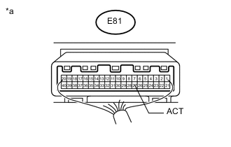
Text in Illustration *a Component with harness connected
(Air Conditioning Amplifier Assembly)
w/o Rear Heater:
-
Remove the air conditioning amplifier assembly with its connectors still connected Click here.
-
Measure the voltage according to the value(s) in the table below.
Standard Voltage Tester Connection Switch Condition Specified Condition E81-27 (ACT) - Body ground
-
Engine idling
-
A/C switch off or on (magnet clutch off)
-
Blower switch LO
Below 1V E81-27 (ACT) - Body ground
-
Engine idling
-
A/C switch on (magnet clutch on)
-
Blower switch LO
4.5 to 5.5 V -
Result Result Proceed to OK A NG (for 1VD-FTV) B NG (for 1GR-FE) C NG (for 1UR-FE) D NG (for 3UR-FE) E -
A
REPLACE AIR CONDITIONING AMPLIFIER ASSEMBLY Click here
B
REPLACE ECM Click here
C
REPLACE ECM Click here
D
REPLACE ECM Click here
E
REPLACE ECM Click here
-