AIR CONDITIONING SYSTEM(for Automatic Air Conditioning System) Heater Control Switch Circuit
DESCRIPTION
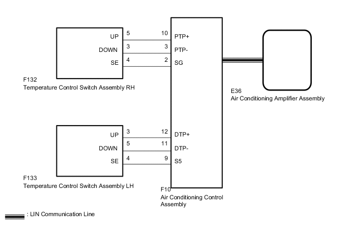
The temperature control switch assembly LH and RH sends the temperature up and down signal to the air conditioning amplifier assembly through the air conditioning control assembly.
WIRING DIAGRAM
PROCEDURE
-
CHECK FOR DTC
-
Clear the DTCs Click here.
-
Check for DTCs Click here.
OK DTC B14B2 is not output..
NG 
GO TO DTC B14B2 Click here
OK 
-
-
CHECK OPERATION
-
Check that the temperature control switches operate.
Result Result Proceed to Temperature control switch LH does not operate A Temperature control switch RH does not operate B Temperature control switch LH and RH do not operate C
B 
INSPECT TEMPERATURE CONTROL SWITCH ASSEMBLY RH Click here
C
CHECK AIR CONDITIONING CONTROL ASSEMBLY Click here
A
-
-
INSPECT TEMPERATURE CONTROL SWITCH ASSEMBLY LH
-
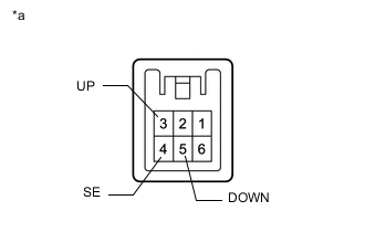
Text in Illustration *a Component without harness connected
(Temperature Control Switch Assembly LH)
Remove the temperature control switch assembly LH Click here.
-
Measure the resistance according to the value(s) in the table below.
Standard Resistance Tester Connection Switch Condition Specified Condition 3 (UP) - 4 (SE) UP switch pressed Below 1 Ω UP switch not pressed 10 kΩ or higher 5 (DOWN) - 4 (SE) DOWN switch pressed Below 1 Ω DOWN switch not pressed 10 kΩ or higher
NG
REPLACE TEMPERATURE CONTROL SWITCH ASSEMBLY LH Click here
OK
-
-
CHECK HARNESS AND CONNECTOR (TEMPERATURE CONTROL SWITCH ASSEMBLY LH - AIR CONDITIONING CONTROL ASSEMBLY)
-
Disconnect the F133 temperature control switch assembly LH connector.
-
Disconnect the F10 air conditioning control assembly connector.
-
Measure the resistance according to the value(s) in the table below.
Standard Resistance Tester Connection Condition Specified Condition F133-3 (UP) - F10-12 (DTP+) Always Below 1 Ω F133-5 (DOWN) - F10-11 (DTP-) Always Below 1 Ω F133-4 (SE) - F10-9 (S5) Always Below 1 Ω F133-3 (UP) - Body ground Always 10 kΩ or higher F133-5 (DOWN) - Body ground Always 10 kΩ or higher F133-4 (SE) - Body ground Always 10 kΩ or higher
OK
REPLACE AIR CONDITIONING CONTROL ASSEMBLY Click here
NG
REPAIR OR REPLACE HARNESS OR CONNECTOR
-
-
INSPECT TEMPERATURE CONTROL SWITCH ASSEMBLY RH
-
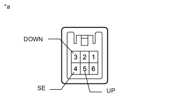
Text in Illustration *a Component without harness connected
(Temperature Control Switch Assembly LH)
Remove the temperature control switch assembly RH Click here.
-
Measure the resistance according to the value(s) in the table below.
Standard Resistance Tester Connection Switch Condition Specified Condition 5 (UP) - 4 (SE) UP switch pressed Below 1 Ω UP switch not pressed 10 kΩ or higher 3 (DOWN) - 4 (SE) DOWN switch pressed Below 1 Ω DOWN switch not pressed 10 kΩ or higher
NG
REPLACE TEMPERATURE CONTROL SWITCH ASSEMBLY RH Click here
OK
-
-
CHECK HARNESS AND CONNECTOR (TEMPERATURE CONTROL SWITCH ASSEMBLY RH - AIR CONDITIONING CONTROL ASSEMBLY)
-
Disconnect the F132 temperature control switch assembly RH connector.
-
Disconnect the F10 air conditioning control assembly connector.
-
Measure the resistance according to the value(s) in the table below.
Standard Resistance Tester Connection Condition Specified Condition F132-5 (UP) - F10-10 (PTP+) Always Below 1 Ω F132-3 (DOWN) - F10-3 (PTP-) Always Below 1 Ω F132-4 (SE) - F10-2 (SG) Always Below 1 Ω F132-5 (UP) - Body ground Always 10 kΩ or higher F132-3 (DOWN) - Body ground Always 10 kΩ or higher F132-4 (SE) - Body ground Always 10 kΩ or higher
OK
REPLACE AIR CONDITIONING CONTROL ASSEMBLY Click here
NG
REPAIR OR REPLACE HARNESS OR CONNECTOR
-
-
CHECK AIR CONDITIONING CONTROL ASSEMBLY
-
Replace the air conditioning control assembly with a new or normally functioning one Click here.
-
Check that the temperature control with temperature control switch LH and RH.
OK Temperature control with temperature control switch LH and RH.
OK
END (AIR CONDITIONING CONTROL ASSEMBLY IS DEFECTIVE)
NG
REPLACE AIR CONDITIONING AMPLIFIER ASSEMBLY Click here
-