AIR CONDITIONING SYSTEM(for Automatic Air Conditioning System) Blower Motor Circuit
DESCRIPTION
The blower with fan motor sub-assembly is operated by signals from the air conditioning amplifier assembly. The blower with fan motor sub-assembly speed signals are transmitted by changes in the duty ratio.
The air conditioning amplifier assembly controls the blower with fan motor sub-assembly speed.
WIRING DIAGRAM
-
w/ Rear Heater:
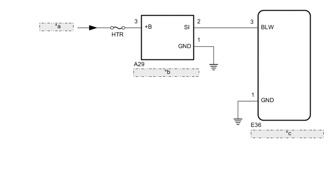
*a from Battery *b Blower with Fan Motor Sub-assembly *c Air Conditioning Amplifier Assembly -
w/o Rear Heater:
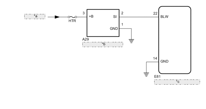
*a from Battery *b Blower with Fan Motor Sub-assembly *c Air Conditioning Amplifier Assembly
CAUTION / NOTICE / HINT
Note
Inspect the fuses for circuits related to this system before performing the following inspection procedure.
PROCEDURE
-
PERFORM ACTIVE TEST USING GTS (BLOWER MOTOR)
-
Select the Active Test, use the GTS to generate a control command, and then check that the blower with fan motor sub-assembly operates Click here.
Air Conditioner Tester Display Test Part Control Range Diagnostic Note Blower Motor Blower with fan motor sub-assembly Min.: 0, Max.: 31 - OK Blower with fan motor sub-assembly is operated normally using GTS.
OK 
PROCEED TO NEXT CIRCUIT INSPECTION SHOWN IN PROBLEM SYMPTOMS TABLE Click here
NG 
-
-
CHECK HARNESS AND CONNECTOR (BLOWER WITH FAN MOTOR SUB-ASSEMBLY - BATTERY AND BODY GROUND)
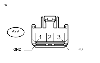
Text in Illustration *a Front view of wire harness connector
(to Blower with Fan Motor Sub-assembly)
-
Disconnect the blower with fan motor sub-assembly connector.
-
Measure the resistance according to the value(s) in the table below.
Standard Resistance Tester Connection Condition Specified Condition A29-1 (GND) - Body ground Always Below 1 Ω -
Measure the voltage according to the value(s) in the table below.
Standard Resistance Tester Connection Condition Specified Condition A29-3 (+B) - Body ground Always 11 to 14 V
NG
REPAIR OR REPLACE HARNESS OR CONNECTOR
OK
-
-
CHECK HARNESS AND CONNECTOR (BLOWER WITH FAN MOTOR SUB-ASSEMBLY - AIR CONDITIONING AMPLIFIER ASSEMBLY)
-
w/ Rear Heater:
-
Disconnect the A29 blower with fan motor sub-assembly connector.
-
Disconnect the E36 air conditioning amplifier assembly connector.
-
Measure the resistance according to the value(s) in the table below.
Standard Resistance Tester Connection Switch Condition Specified Condition A29-2 (SI) - E36-3 (BLW) Always Below 1 Ω A29-2 (SI) or E36-3 (BLW) - Body ground Always 10 kΩ or higher
-
-
w/o Rear Heater:
-
Disconnect the A29 blower with fan motor sub-assembly connector.
-
Disconnect the E81 air conditioning amplifier assembly connector.
-
Measure the resistance according to the value(s) in the table below.
Standard Resistance Tester Connection Switch Condition Specified Condition A29-2 (SI) - E81-22 (BLW) Always Below 1 Ω A29-2 (SI) or E81-22 (BLW) - Body ground Always 10 kΩ or higher
-
NG
REPAIR OR REPLACE HARNESS OR CONNECTOR
OK
-
-
CHECK AIR CONDITIONING AMPLIFIER ASSEMBLY
-
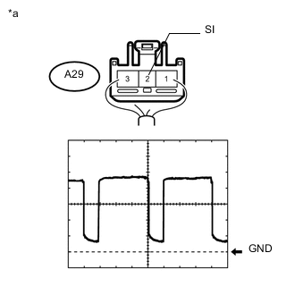
Text in Illustration *a Component with harness connected
(Blower with Fan Motor Sub-assembly)
Using an oscilloscope, check the waveform
Measurement Condition Item Content Terminal No. (Symbol) A29-2 (SI) - Body ground Tool Setting 1 V/DIV., 500 μs/DIV. Condition
-
Ignition switch ON
-
Blower switch LO
OK Waveform is as shown in the illustration. Tech Tips
Waveform varies with the blower level.
-
OK
REPLACE BLOWER WITH FAN MOTOR SUB-ASSEMBLY Click here
NG
-
-
CHECK BLOWER WITH FAN MOTOR SUB-ASSEMBLY
-
Replace the blower with fan motor sub-assembly with a new or known good one Click here.
-
Check that the air conditioning system is operated normally.
OK Air conditioning system is operated normally.
OK
END (BLOWER WITH FAN MOTOR SUB-ASSEMBLY WAS DEFECTIVE)
NG
REPLACE AIR CONDITIONING AMPLIFIER ASSEMBLY Click here
-