AIR CONDITIONING SYSTEM(for Automatic Air Conditioning System) TERMINALS OF ECU
-
CHECK AIR CONDITIONING AMPLIFIER ASSEMBLY (w/ Rear Heater)

-
Disconnect the E36 and E35 air conditioning amplifier assembly connectors.
-
Measure the voltage and resistance according to the value(s) in the table below.
Terminal No. (Symbol) Wiring Color Terminal Description Condition Specified Condition E35-6 (E1) - Body ground W-B - Body ground Ground Always Below 1 Ω E35-17 (RHTR) - E35-31 (SGND) W - GR Power supply for duct sensor RH
-
Ignition switch ON
-
Passenger side duct sensor temperature: 25°C (77°F)
4850 to 5150 Ω E35-18 (RHTL) - E35-31 (SGND) V - GR Power supply for duct sensor LH
-
Ignition switch ON
-
Passenger side duct sensor temperature: 25°C (77°F)
4850 to 5150 Ω E36-1 (GND) - Body ground BR - Body ground Ground Always Below 1 Ω E36-5 (IG+) - E36-1 (GND) G - BR Ignition power supply Ignition switch ON 11 to 14 V Ignition switch off Below 1 V E36-6 (+B1) - E36-1 (GND) LG - BR Battery power supply Always 11 to 14 V E36-7 (+B2) - E36-1 (GND) LG - BR Battery power supply Always 11 to 14 V -
-
Reconnect the E36 and E35 air conditioning amplifier assembly connectors.
-
Measure the voltage and resistance according to the value(s) in the table below.
Terminal No. (Symbol) Wiring Color Terminal Description Condition Specified Condition E35-1 (SG-1) - Body ground B - Body ground Ground for room temperature sensor (for front) Always Below 1 Ω E35-9 (PRE) - E35-32 (SG-2) R - G Air conditioning pressure sensor signal
-
Ignition switch ON
-
A/C switch off
0.63 to 4.78 V
-
Engine idling
-
A/C switch on
-
Blower switch LO
-
Refrigerant pressure is normal
0.63 to 4.78 V Refrigerant pressure: Abnormal (less than 177 kPa [1.8 kgf/cm2, 26 psi])
Below 0.63 V Refrigerant pressure: Abnormal (more than 3079 kPa [31.4 kgf/cm2, 446 psi])
4.78 V or higher E35-10 (TAM) - E35-32 (SG-2) V - G Ambient temperature sensor signal
-
Ignition switch ON
-
Ambient temperature: 25°C (77°F)
1.4 to 1.6 V
-
Ignition switch ON
-
Ambient temperature: 50°C (122°F)
0.7 to 0.9 V E35-11 (TEC) - E35-33 (SG) W - P Evaporator temperature sensor signal (for rear)
-
Ignition switch ON
-
Evaporator temperature: 15°C (59°F)
1.4 to 1.8 V E35-13 (S5-3) - E35-32 (SG-2) LG - G Power supply for air conditioner pressure Ignition switch ON 4.75 to 5.25 V E35-16 (TR) - E35-1 (SG-1) W - B Room temperature sensor signal (for front)
-
Ignition switch ON
-
Front side interior temperature: 25°C (77°F)
1.9 to 2.1 V Room temperature sensor signal (for front)
-
Ignition switch ON
-
Front side interior temperature: 50°C (122°F)
1.0 to 2.0 V E35-21 (TR) - E35-33 (SG) R - P Room temperature sensor signal (for rear LH)
-
Ignition switch ON
-
Vehicle interior temperature: 25°C (77°F)
1.9 to 2.1 V
-
Ignition switch ON
-
Vehicle interior temperature: 50°C (122°F)
1.0 to 1.2 V E35-22 (TSET) - E35-33 (SG) R - P Room temperature sensor signal (for rear RH)
-
Ignition switch ON
-
Vehicle interior temperature: 25°C (77°F)
1.9 to 2.1 V
-
Ignition switch ON
-
Vehicle interior temperature: 50°C (122°F)
1.0 to 1.2 V E35-28 (SW 1) - Body ground*1 P - Body ground Idle up switch operation signal
-
Engine running
-
A/C switch on
-
Blower switch on (LO level)
-
Idle up switch off → on
Below 1 V 14 V E35-29 (COOL) - Body ground*4 W - Body ground Cool box operation signal
-
Ignition switch ON
-
Cool box switch on
Below 1 V
-
Ignition switch ON
-
Cool box switch off
11 to 14 V E35-30 (LOCK) - E35-32 (SG-2) L - G Compressor lock sensor signal
-
Engine idling
-
A/C switch on (magnet clutch on)
-
Blower switch: LO
Pulse generation
(see waveform 1)
E35-31 (SGND) - Body ground GR - Body ground Ground for duct sensor RH Always Below 1 Ω E35-32 (SG-2) - Body ground G - Body ground Ground for pressure sensor, cooler compressor Always Below 1 Ω E35-33 (SG) - Body ground P - Body ground Ground for evaporator temperature sensor signal (for rear), rear room temperature sensor signal LH and RH Always Below 1 Ω E36-3 (BLW) - E36-1 (GND) R - BR Blower motor control signal
-
Ignition switch ON
-
Blower switch: LO
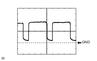
Pulse generation
(see waveform 2)
-
Ignition switch ON
-
Blower switch: off
4.5 to 5.5 V E36-8 (PTC1) - Body ground*2 W - Body ground Quick heater assembly operation signal
-
Engine idling
-
Set temperature: MAX HOT (HI)
-
Engine coolant temperature: Below 65°C (149°F)
-
Ambient temperature: Below 10°C (50°F)
-
Blower switch: off → on (after 10 seconds)
11 to 14 V → Below 1 V E36-11 (AC1) - Body ground L - Body ground Compressor operation signal
-
Engine idling
-
Blower switch LO
-
A/C switch off
11 to 14 V
-
Engine idling
-
Blower switch LO
-
A/C switch on
Below 1 V E36-12 (RBUG) - Body ground BR - Body ground Ground for BUS IC (for rear) Always Below 1 Ω E36-13 (RBUS) - E36-12 (RBUG) R - BR BUS IC control signal (for rear) Ignition switch ON Pulse generation E36-14 (RBBU) - E36-12 (RBUG) L - BR Power supply for BUS IC (for rear) Always 11 to 14 V E36-17 (BLWH) - E36-1 (GND) L - BR Blower motor control signal (for rear)
-
Ignition switch ON
-
Blower switch: LO
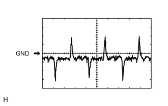
Pulse generation
(see waveform 3)
E36-18 (MGC) - E36-1 (GND) R - BR Magnet clutch operation signal
-
Engine idling
-
Blower switch: LO
-
A/C switch on (magnet clutch on)
Below 1 V
-
Engine idling
-
Blower switch: LO
-
A/C switch on or off (magnet clutch off)
11 to 14 V E36-19 (RMGV) - E36-1 (GND) B - BR Rear cooling unit expansion valve signal
-
Ignition switch ON
-
Blower switch LO
-
A/C switch on
11 to 14 V E36-22 (ACT) - Body ground G - Body ground Compressor operation signal
-
Engine idling
-
A/C switch off or on (magnet clutch off)
Below 1 V
-
Engine idling
-
A/C switch on (magnet clutch on)
11 to 14 V E36-23 (ALT) - Body ground R - Body ground Generator assembly signal Ignition switch ON Pulse generation E36-24 (PTC3) - Body ground*2 R - Body ground Quick heater assembly operation signal
-
Engine idling
-
Set temperature: MAX HOT (HI)
-
Engine coolant temperature: Below 65°C (149°F)
-
Ambient temperature: Below 10°C (50°F)
-
Blower switch: off → on (after 20 seconds)
11 to 14 V → Below 1 V E36-26 (PTC2) - Body ground*2 B - Body ground Quick heater assembly operation signal
-
Engine idling
-
Set temperature: MAX HOT (HI)
-
Engine coolant temperature: Below 65°C (149°F)
-
Ambient temperature: Below 10°C (50°F)
-
Blower switch: off → on (after 30 seconds)
11 to 14 V → Below 1 V E36-27 (CFN+) - Body ground*3 R - Body ground Condenser fan operation signal Ignition switch ON 11 to 14 V E36-29 (ECOS) - Body ground*5 B - Body ground Integration control and panel assembly (ECO mode switch) operation signal
-
Ignition switch ON
-
Integration control and panel assembly (ECO mode switch) on
Below 1 V
-
Ignition switch ON
-
Integration control and panel assembly (ECO mode switch) off
11 to 14 V E36-32 (MGCA) - Body ground*1 P - Body ground Viscous with magnet clutch operation signal
-
Engine idling
-
Idle up switch on
Below 1 V z72-1 (BUS G) - Body ground - Ground for BUS IC (for front) Always Below 1 Ω z72-2 (BUS) - z72-1 (BUS G) - BUS IC control signal (for front) Ignition switch ON Pulse generation z72-3 (B BUS) - z72-1 (BUS G) - Power supply for BUS IC (for front) Always 11 to 14 V z72-11 (TE) - z72-12 (SG) - Evaporator temperature sensor signal
-
Ignition switch ON
-
Evaporator temperature: 15°C (59°F)
1.0 to 1.2 V z72-12 (SG) - Body ground - Ground for evaporator temperature sensor Always Below 1 Ω
-
*1: w/ Viscous Heater
-
*2: w/ PTC Heater
-
*3: w/ Condenser Fan
-
*4: w/ Cool Box
-
*5: w/ ECO Mode Switch
-
-
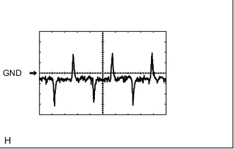
Using an oscilloscope, check waveform 1.
Tech Tips
When the engine speed is increased, the duty ratio changes accordingly.
Item Content Terminal No. (Symbol) E35-30 (LOCK) - E35-32 (SG-2) Tool Setting 200 mV/DIV., 10 ms/DIV. Condition
-
Engine idling
-
A/C switch on (magnet clutch on)
-
Blower switch: LO
-
-

Using an oscilloscope, check waveform 2.
Tech Tips
When the blower level is increased, the duty ratio changes accordingly.
Item Content Terminal No. (Symbol) E36-3 (BLW) - E36-1 (GND) Tool Setting 1 V/DIV., 500 μs/DIV. Condition
-
Ignition switch ON
-
Blower switch: LO
-
-
Using an oscilloscope, check waveform 3.
Tech Tips
When the rear blower level is increased, the duty ratio changes accordingly.
Item Content Terminal No. (Symbol) E36-17 (BLWH) - E36-1 (GND) Tool Setting 2 V/DIV., 500 μs/DIV. Condition
-
Ignition switch ON
-
Blower switch: LO
-
-
-
CHECK AIR CONDITIONING AMPLIFIER ASSEMBLY (w/o Rear Heater)
-
Disconnect the E81 air conditioning amplifier assembly connector.
-
Measure the voltage and resistance according to the value(s) in the table below.
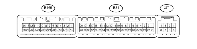
Terminal No. (Symbol) Wiring Color Terminal Description Condition Specified Condition E81-1 (IG+) - E81-14 (GND) G - BR Ignition power supply Ignition switch ON 11 to 14 V Ignition switch off Below 1 V E81-14 (GND) - Body ground BR - Body ground Ground Always Below 1 Ω E81-21 (+B1) - E81-14 (GND) LG - BR Battery power supply Always 11 to 14 V -
Reconnect the E81 air conditioning amplifier assembly connector.
-
Measure the voltage, resistance and waveform according to the value(s) in the table below.
Terminal No. (Symbol) Wiring Color Terminal Description Condition Specified Condition E81-3 (PTC2) - Body ground*2 B - Body ground Quick heater assembly operation signal
-
Engine idling
-
Set temperature: MAX HOT (HI)
-
Engine coolant temperature: Below 65°C (149°F)
-
Ambient temperature: Below 10°C (50°F)
-
Blower switch: off → on (after 30 seconds)
11 to 14 V → Below 1 V E81-4 (SW 1) - Body ground*1 P - Body ground Idle up switch operation signal
-
Engine running
-
A/C switch on
-
Blower switch on (LO level)
-
Idle up switch off → on
Below 1 V 14 V E81-5 (TAM) - E81-13 (SG-2) V - G Ambient temperature sensor signal
-
Ignition switch ON
-
Ambient temperature: 25°C (77°F)
1.4 to 1.6 V
-
Ignition switch ON
-
Ambient temperature: 50°C (122°F)
0.7 to 0.9 V E81-8 (LOCK) - E81-13 (SG-2) L - G Compressor lock sensor signal
-
Engine idling
-
A/C switch on (magnet clutch on)
-
Blower switch: LO
Pulse generation
(see waveform 1)
E81-9 (PRE) - E81-13 (SG-2) R - G Air conditioning pressure sensor signal
-
Ignition switch ON
-
A/C switch off
0.63 to 4.78 V
-
Engine idling
-
A/C switch on
-
Blower switch LO
-
Refrigerant pressure is normal
0.63 to 4.78 V Refrigerant pressure: Abnormal (less than 177 kPa [1.8 kgf/cm2, 26 psi])
Below 0.63 V Refrigerant pressure: Abnormal (more than 3079 kPa [31.4 kgf/cm2, 446 psi])
4.78 V or higher E81-13 (SG-2) - Body ground G - Body ground Ground for pressure sensor, cooler compressor Always Below 1 Ω E81-17 (MGCA) - Body ground*1 P - Body ground Viscous with magnet clutch operation signal
-
Engine idling
-
Idle up switch on
Below 1 V E81-18 (RCRL) - Body ground B - Body ground Rear cooler control relay operation signal
-
Ignition switch ON
-
Rear blower switch off
Below 1 V
-
Ignition switch ON
-
Rear blower switch LO
11 to 14 V E81-19 (CFN+) - Body ground*3 R - Body ground Condenser fan operation signal Ignition switch ON 11 to 14 V E81-20 (MGC) - E81-14 (GND) R - BR Magnet clutch operation signal
-
Engine idling
-
Blower switch: LO
-
A/C switch on (magnet clutch on)
Below 1 V
-
Engine idling
-
Blower switch: LO
-
A/C switch on or off (magnet clutch off)
11 to 14 V E81-22 (BLW) - E81-14 (GND) R - BR Blower motor control signal
-
Ignition switch ON
-
Blower switch: LO
Pulse generation
(see waveform 2)
-
Ignition switch ON
-
Blower switch: off
4.5 to 5.5 V E81-23 (AC1) - Body ground L - Body ground Compressor operation signal
-
Engine idling
-
Blower switch LO
-
A/C switch off
11 to 14 V
-
Engine idling
-
Blower switch LO
-
A/C switch on
Below 1 V E81-24 (COOL) - Body ground*4 W - Body ground Cool box operation signal
-
Ignition switch ON
-
Cool box switch on
Below 1 V
-
Ignition switch ON
-
Cool box switch off
11 to 14 V E81-25 (ALT) - Body ground R - Body ground Generator assembly signal Ignition switch ON Pulse generation E81-27 (ACT) - Body ground G - Body ground Compressor operation signal
-
Engine idling
-
A/C switch off or on (magnet clutch off)
Below 1 V
-
Engine idling
-
A/C switch on (magnet clutch on)
11 to 14 V E81-30 (S5-3) - E81-13 (SG-2) LG - G Power supply for air conditioner pressure Ignition switch ON 4.75 to 5.25 V E81-36 (PTC3) - Body ground*2 R - Body ground Quick heater assembly operation signal
-
Engine idling
-
Set temperature: MAX HOT (HI)
-
Engine coolant temperature: Below 65°C (149°F)
-
Ambient temperature: Below 10°C (50°F)
-
Blower switch: off → on (after 20 seconds)
11 to 14 V → Below 1 V E81-40 (PTC1) - Body ground*2 W - Body ground Quick heater assembly operation signal
-
Engine idling
-
Set temperature: MAX HOT (HI)
-
Engine coolant temperature: Below 65°C (149°F)
-
Ambient temperature: Below 10°C (50°F)
-
Blower switch: off → on (after 10 seconds)
11 to 14 V → Below 1 V E165-4 (TR) - E165-8 (SG-1) W - B Room temperature sensor signal
-
Ignition switch ON
-
Front side interior temperature: 25°C (77°F)
1.9 to 2.1 V Room temperature sensor signal
-
Ignition switch ON
-
Front side interior temperature: 50°C (122°F)
1.0 to 2.0 V E165-6 (ECOS) - Body ground*5 B - Body ground Integration control and panel assembly (ECO mode switch) operation signal
-
Ignition switch ON
-
Integration control and panel assembly (ECO mode switch) on
Below 1 V
-
Ignition switch ON
-
Integration control and panel assembly (ECO mode switch) off
11 to 14 V E165-8 (SG-1) - Body ground B - Body ground Ground for room temperature sensor Always Below 1 Ω z71-2 (BUS G) - Body ground - Ground for BUS IC Always Below 1 Ω z71-3 (BUS) - z71-2 (BUS G) - BUS IC control signal Ignition switch ON Pulse generation z71-4 (B BUS) - z71-2 (BUS G) - Power supply for BUS IC Always 11 to 14 V z71-5(SG) - Body ground - Ground for evaporator temperature sensor Always Below 1 Ω z71-5 (GS) - z71-6 (TE) - Evaporator temperature sensor signal
-
Ignition switch ON
-
Evaporator temperature: 15°C (59°F)
1.0 to 1.2 V
-
*1: w/ Viscous Heater
-
*2: w/ PTC Heater
-
*3: w/ Condenser Fan
-
*4: w/ Cool Box
-
*5: w/ ECO Mode Switch
-
-
Using an oscilloscope, check waveform 1.
Compressor Lock Sensor Signal Item Content Terminal No. (Symbol) E81-8 (LOCK) - E81-13 (SG-2) Tool Setting 200 mV/DIV., 10 ms/DIV. Condition
-
Engine idling
-
Blower switch: LO
-
A/C switch: On
Tech Tips
When the rear blower level is increased, the duty ratio changes accordingly.
-
-
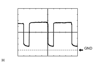
Using an oscilloscope, check waveform 2.
Blower Motor Control Signal Item Content Terminal No. (Symbol) E81-22 (BLW) - E81-14 (GND) Tool Setting 1 V/DIV., 500 μs/DIV. Condition
-
Ignition switch ON
-
Blower switch: LO
Tech Tips
When the blower level is increased, the duty ratio changes accordingly.
-
-
-
CHECK AIR CONDITIONING CONTROL ASSEMBLY (w/o Navigation System [w/o Entry and Start System])

-
Disconnect the F10 air conditioning control assembly connector.
-
Measure the resistance and voltage according to the value(s) in the table below.
Terminal No. (Symbol) Wiring Color Terminal Description Condition Specified Condition F10-7 (IG+) - F10-1 (GND) B - W-B Ignition power supply Ignition switch ON 11 to 14 V Ignition switch off Below 1 V F10-1 (GND) - Body ground W-B - Body ground Ground Always Below 1 Ω -
Reconnect the F10 air conditioning control assembly connector.
-
Measure the resistance and voltage according to the value(s) in the table below.
Terminal No. (Symbol) Wiring Color Terminal Description Condition Specified Condition F10-12 (DTP+) - F10-1 (GND) GR - W-B Temperature up switch signal Temperature up switch not pressed Below 1 V Temperature up switch pressed Alternating between 3.5 V or higher and below 1 V F10-10 (PTP+) - F10-1 (GND) L - W-B Temperature up switch signal Temperature up switch not pressed Below 1 V Temperature up switch pressed Alternating between 3.5 V or higher and below 1 V F10-9 (S5) - F10-1 (GND) SB - W-B Signal ground Always Below 1 Ω F10-11 (DTP-) - F10-1 (GND) B - W-B Temperature down switch signal Temperature down switch not pressed Below 1 V Temperature down switch pressed Alternating between 3.5 V or higher and below 1 V F10-3 (PTP-) - F10-1 (GND) V - W-B Temperature down switch signal Temperature down switch not pressed Below 1 V Temperature down switch pressed Alternating between 3.5 V or higher and below 1 V F10-2 (SG) - F10-1 (GND) R - W-B Signal ground Always Below 1 Ω
-
-
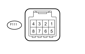
CHECK AIR CONDITIONING CONTROL ASSEMBLY (w/o Navigation System [w/ Entry and Start System])
-
Disconnect the F111 air conditioning control assembly connector.
-
Measure the resistance and voltage according to the value(s) in the table below.
Terminal No. (Symbol) Wiring Color Terminal Description Condition Specified Condition F111-5 (IG+) - F111-8 (GND) B - W-B Ignition power supply Ignition switch ON 11 to 14 V Ignition switch off Below 1 V F111-8(GND) - Body ground W-B - Body ground Ground Always Below 1 Ω
-
-
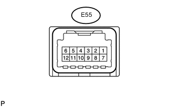
CHECK NO. 2 AIR CONDITIONING CONTROL ASSEMBLY (w/ Rear Heater)
-
Disconnect the E55 No. 2 air conditioning control assembly connector.
-
Measure the resistance and voltage according to the value(s) in the table below.
Terminal No. (Symbol) Wiring Color Terminal Description Condition Specified Condition E55-6 (IG) - E55-1 (E) B - W-B Ignition power supply Always 11 to 14 V E55-1 (E) - Body ground W-B - Body ground Ground Always Below 1 Ω
-
-
MULTI-DISPLAY ASSEMBLY (w/ Navigation System) Click here
-
MULTI-MEDIA MODULE RECEIVER ASSEMBLY (w/ Navigation System) Click here