SEAT BELT WARNING SYSTEM Front Passenger Side Seat Belt Warning Light Malfunction
DESCRIPTION
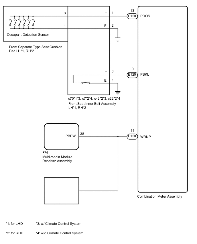
The combination meter detects the state of the front seat inner belt assembly (for Front Passenger Side) when the front passenger seat is occupied with the ignition switch ON. If the front passenger seat belt is not fastened, the front passenger side seat belt warning light on the multi-media module receiver assembly*1 (clock assembly*2) blinks. If the seat belt is fastened, the warning light goes off.
-
*1: w/ Navigation System
-
*2: w/o Navigation System
WIRING DIAGRAM
CAUTION / NOTICE / HINT
Note
Inspect the fuses for circuits related to this system before performing the following inspection procedure.
PROCEDURE
-
CHECK VEHICLE TYPE
-
Check the vehicle type.
Result Result Proceed to for LHD A for RHD B
B 
CHECK FOR DTC Click here
A 
-
-
CHECK FOR DTC
-
Check for DTCs.
Result Result Proceed to DTC is not output A CAN communication system DTC is output (for LHD with Central Gateway ECU) B CAN communication system DTC is output (for LHD without Central Gateway ECU) C Airbag system DTC is output D
B 
Go to CAN COMMUNICATION SYSTEM Click here
C
Go to CAN COMMUNICATION SYSTEM Click here
D
Go to AIRBAG SYSTEM Click here
A
-
-
READ VALUE USING GTS (PASSENGER SIDE BUCKLE SWITCH)
-
Check the Data List for proper functioning of the front passenger side seat belt buckle switch.
Combination Meter Tester Display Measurement Item/Range Normal Condition Diagnostic Note P-Seatbelt Buckle SW Front passenger side seat belt buckle signal / ON or OFF ON: Front passenger side seat belt is fastened
OFF: Front passenger side seat belt is unfastened
- Passenger Occupant Detection Switch Occupant detection sensor signal / ON or OFF ON: Front passenger seat occupied
OFF: Front passenger seat not occupied
- Result Result Proceed to ON or OFF is displayed on the GTS screen according (w/ Navigation System) A ON or OFF is displayed on the GTS screen according (w/o Navigation System) B ON or OFF is not displayed normally on the GTS screen according to the front passenger side seat belt condition C ON or OFF is not displayed normally on the GTS screen according to the front passenger seat condition (occupied or unoccupied) D
B
CHECK HARNESS AND CONNECTOR (CLOCK ASSEMBLY - COMBINATION METER ASSEMBLY, BATTERY AND BODY GROUND) Click here
C
INSPECT FRONT SEAT INNER BELT ASSEMBLY LH Click here
D
INSPECT FRONT SEPARATE TYPE SEAT CUSHION PAD LH (OCCUPANT DETECTION SENSOR) Click here
A
-
-
CHECK HARNESS AND CONNECTOR (MULTI-MEDIA MODULE RECEIVER ASSEMBLY - COMBINATION METER ASSEMBLY, BATTERY AND BODY GROUND)
-
Disconnect the F77 multi-media module receiver assembly connector.
-
Disconnect the E119 combination meter assembly connector.
-
Measure the resistance according to the value(s) in the table below.
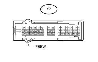
Standard Resistance Tester Connection Condition Specified Condition F77-38 (PBEW) - E119-11 (WRNP) Always Below 1 Ω F77-38 (PBEW) or E119-11 (WRNP) - Body ground Always 10 kΩ or higher
NG
REPAIR OR REPLACE HARNESS OR CONNECTOR
OK
-
-
CHECK MULTI-MEDIA MODULE RECEIVER ASSEMBLY
-
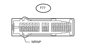
Text in Illustration *a Front view of wire harness connector
(to Multi-media Module Receiver Assembly)
Disconnect the F77 multi-media module receiver assembly connector.
-
Measure the voltage according to the value(s) in the table below.
Standard Voltage Tester Connection Switch Condition Specified Condition F77-38 (WRNP) - Body ground Ignition switch ON 11 to 14 V
OK
REPLACE COMBINATION METER ASSEMBLY Click here
NG
REPLACE MULTI-MEDIA MODULE RECEIVER ASSEMBLY Click here
-
-
CHECK HARNESS AND CONNECTOR (CLOCK ASSEMBLY - COMBINATION METER ASSEMBLY, BATTERY AND BODY GROUND)
-
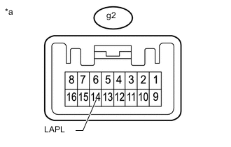
Disconnect the g2 clock assembly connector.
-
Disconnect the E119 combination meter assembly connector.
-
Measure the resistance according to the value(s) in the table below.
Standard Resistance Tester Connection Condition Specified Condition g2-14 (LAPL) or E119-11 (WRNP) - Body ground Always 10 kΩ or higher g2-14 (LAPL) - E119-11 (WRNP) Always Below 1 Ω
NG
REPAIR OR REPLACE HARNESS OR CONNECTOR
OK
-
-
CHECK CLOCK ASSEMBLY
-

Text in Illustration *a Front view of wire harness connector
(to Clock Assembly)
Disconnect the g2 clock assembly connector.
-
Measure the voltage according to the value(s) in the table below.
Standard Voltage Tester Connection Switch Condition Specified Condition g2-14 (LAPL) - Body ground Ignition switch ON 11 to 14 V
OK
REPLACE COMBINATION METER ASSEMBLY Click here
NG
REPLACE CLOCK ASSEMBLY Click here
-
-
INSPECT FRONT SEAT INNER BELT ASSEMBLY LH
-
Remove the front seat inner belt assembly LH.
-
except Bench Seat: Click here
-
for Bench Seat: Click here
-
-
Inspect the front seat inner belt assembly LH.
-
except Bench Seat: Click here
-
for Bench Seat: Click here
Result Result Proceed to OK A NG (except Bench Seat) B NG (for Bench seat) C -
B
REPLACE FRONT SEAT INNER BELT ASSEMBLY (for Front Passenger Side) Click here
C
REPLACE FRONT SEAT INNER BELT ASSEMBLY (for Front Passenger Side) Click here
A
-
-
CHECK HARNESS AND CONNECTOR (FRONT SEAT INNER BELT ASSEMBLY LH - COMBINATION METER ASSEMBLY, BATTERY AND BODY GROUND)
-
Disconnect the c7 front seat inner belt assembly LH connector.
-
Disconnect the E120 combination meter assembly connector.
-
Measure the resistance according to the value(s) in the table below.
Standard Resistance Tester Connection Condition Specified Condition c7-3 (+) - E120-9 (PBKL) Always Below 1 Ω c7-3 (+) or E120-9 (PBKL) - Body ground Always 10 kΩ or higher c7-4 (E) - Body ground Always Below 1 Ω
OK
REPLACE COMBINATION METER ASSEMBLY Click here
NG
REPAIR OR REPLACE HARNESS OR CONNECTOR
-
-
INSPECT FRONT SEPARATE TYPE SEAT CUSHION PAD LH (OCCUPANT DETECTION SENSOR)
-
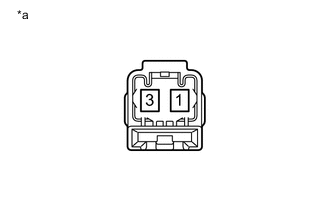
Text in Illustration *a Component without harness connected
(Occupant Detection Sensor)
Remove the front separate type seat cushion pad LH.
-
for Manual Seat: Click here
-
for Power Seat: Click here
-
for Bench Seat: Click here
-
-
Measure the resistance according to the value(s) in the table below.
Standard Resistance Tester Connection Condition Specified Condition 1 - 3 Front passenger seat occupied Below 100 Ω 1 - 3 Front passenger seat not occupied 10 kΩ or higher Result Result Proceed to OK A NG (for Manual Seat) B NG (for Power Seat) C NG (for Bench Seat) D
B
REPLACE FRONT SEPARATE TYPE SEAT CUSHION PAD Click here
C
REPLACE FRONT SEPARATE TYPE SEAT CUSHION PAD Click here
D
REPLACE FRONT SEPARATE TYPE SEAT CUSHION PAD Click here
A
-
-
INSPECT FRONT SEAT INNER BELT ASSEMBLY LH
-
Remove the front seat inner belt assembly LH.
-
except Bench Seat: Click here
-
for Bench Seat: Click here
-
-
Inspect the front seat inner belt assembly LH.
-
except Bench Seat: Click here
-
for Bench Seat: Click here
Result Result Proceed to OK A NG (except Bench Seat) B NG (for Bench seat) C -
B
REPLACE FRONT SEAT INNER BELT ASSEMBLY (for Front Passenger Side) Click here
C
REPLACE FRONT SEAT INNER BELT ASSEMBLY (for Front Passenger Side) Click here
A
-
-
CHECK HARNESS AND CONNECTOR (FRONT SEAT INNER BELT LH - COMBINATION METER ASSEMBLY AND BODY GROUND)
-
Disconnect the c7 front seat inner belt assembly LH connector.
-
Disconnect the E119 combination meter assembly connector.
-
Measure the resistance according to the value(s) in the table below.
Standard Resistance Tester Connection Condition Specified Condition c7-1 (+) - E119-13 (PODS) Always Below 1 Ω c7-1 (+) or E119-13 (PODS) - Body ground Always 10 kΩ or higher c7-2 (E) - Body ground Always Below 1 Ω
OK
REPLACE COMBINATION METER ASSEMBLY Click here
NG
REPAIR OR REPLACE HARNESS OR CONNECTOR
-
-
CHECK FOR DTC
-
Check for DTCs.
Result Result Proceed to DTC is not output A CAN communication system DTC is output (for RHD with Central Gateway ECU) B CAN communication system DTC is output (for RHD without Central Gateway ECU) C Airbag system DTC is output D
B
Go to CAN COMMUNICATION SYSTEM Click here
C
Go to CAN COMMUNICATION SYSTEM Click here
D
Go to AIRBAG SYSTEM Click here
A
-
-
READ VALUE USING GTS (PASSENGER SIDE BUCKLE SWITCH)
-
Check the Data List for proper functioning of the front passenger side seat belt buckle switch.
Combination Meter Tester Display Measurement Item/Range Normal Condition Diagnostic Note P-Seatbelt Buckle SW Front passenger side seat belt buckle signal / ON or OFF ON: Front passenger side seat belt is fastened
OFF: Front passenger side seat belt is unfastened
- Passenger Occupant Detection Switch Occupant detection sensor signal / ON or OFF ON: Front passenger seat occupied
OFF: Front passenger seat not occupied
- Result Result Proceed to ON or OFF is displayed on the GTS screen according (w/ Navigation System) A ON or OFF is displayed on the GTS screen according (w/o Navigation System) B ON or OFF is not displayed normally on the GTS screen according to the front passenger side seat belt condition C ON or OFF is not displayed normally on the GTS screen according to the front passenger seat condition (occupied or unoccupied) D
B
CHECK HARNESS AND CONNECTOR (CLOCK ASSEMBLY - COMBINATION METER ASSEMBLY, BATTERY AND BODY GROUND) Click here
C
INSPECT FRONT SEAT INNER BELT ASSEMBLY RH Click here
D
INSPECT FRONT SEPARATE TYPE SEAT CUSHION PAD RH (OCCUPANT DETECTION SENSOR) Click here
A
-
-
CHECK HARNESS AND CONNECTOR (MULTI-MEDIA MODULE RECEIVER ASSEMBLY - COMBINATION METER ASSEMBLY, BATTERY AND BODY GROUND)
-
Disconnect the F77 multi-media module receiver assembly connector.
-
Disconnect the E119 combination meter assembly connector.
-
Measure the resistance according to the value(s) in the table below.
Standard Resistance Tester Connection Condition Specified Condition F77-38 (PBEW) - E119-11 (WRNP) Always Below 1 Ω F77-38 (PBEW) or E119-11 (WRNP) - Body ground Always 10 kΩ or higher
NG
REPAIR OR REPLACE HARNESS OR CONNECTOR
OK
-
-
CHECK COMBINATION METER ASSEMBLY
-
Text in Illustration *a Front view of wire harness connector
(to Multi-media Module Receiver Assembly)
Disconnect the F77 multi-media module receiver assembly connector.
-
Measure the voltage according to the value(s) in the table below.
Standard Voltage Tester Connection Switch Condition Specified Condition F77-38 (PBEW) - Body ground Ignition switch ON 11 to 14 V
OK
REPLACE COMBINATION METER ASSEMBLY Click here
NG
REPLACE MULTI-MEDIA MODULE RECEIVER ASSEMBLY Click here
-
-
CHECK HARNESS AND CONNECTOR (CLOCK ASSEMBLY - COMBINATION METER ASSEMBLY, BATTERY AND BODY GROUND)
-
Disconnect the g2 clock assembly connector.
-
Disconnect the E119 combination meter assembly connector.
-
Measure the resistance according to the value(s) in the table below.
Standard Resistance Tester Connection Condition Specified Condition g2-14 (LAPL) or E119-11 (WRNP) - Body ground Always 10 kΩ or higher g2-14 (LAPL) - E119-11 (WRNP) Always Below 1 Ω
NG
REPAIR OR REPLACE HARNESS OR CONNECTOR
OK
-
-
CHECK CLOCK ASSEMBLY
-
Text in Illustration *a Front view of wire harness connector
(to Clock Assembly)
Disconnect the g2 clock assembly connector.
-
Measure the voltage according to the value(s) in the table below.
Standard Voltage Tester Connection Switch Condition Specified Condition g2-14 (LAPL) - Body ground Ignition switch ON 11 to 14 V
OK
REPLACE COMBINATION METER ASSEMBLY Click here
NG
REPLACE CLOCK ASSEMBLY Click here
-
-
INSPECT FRONT SEAT INNER BELT ASSEMBLY RH
-
Remove the front seat inner belt assembly RH.
-
except Bench Seat: Click here
-
for Bench Seat: Click here
-
-
Inspect the front seat inner belt assembly RH.
-
except Bench Seat: Click here
-
for Bench Seat: Click here
Result Result Proceed to OK A NG (except Bench Seat) B NG (for Bench seat) C -
B
REPLACE FRONT SEAT INNER BELT ASSEMBLY (for Front Passenger Side) Click here
C
REPLACE FRONT SEAT INNER BELT ASSEMBLY (for Front Passenger Side) Click here
A
-
-
CHECK HARNESS AND CONNECTOR (FRONT SEAT INNER BELT ASSEMBLY RH - COMBINATION METER ASSEMBLY, BATTERY AND BODY GROUND)
-
Disconnect the c22 front seat inner belt assembly RH connector.
-
Disconnect the E120 combination meter assembly connector.
-
Measure the resistance according to the value(s) in the table below.
Standard Resistance Tester Connection Condition Specified Condition c22-3 (+) - E120-9 (PBKL) Always Below 1 Ω c22-3 (+) or E120-9 (PBKL) - Body ground Always 10 kΩ or higher c22-4 (E) - Body ground Always Below 1 Ω
OK
REPLACE COMBINATION METER ASSEMBLY Click here
NG
REPAIR OR REPLACE HARNESS OR CONNECTOR
-
-
INSPECT FRONT SEPARATE TYPE SEAT CUSHION PAD RH (OCCUPANT DETECTION SENSOR)
-
Remove the front separate type seat cushion pad RH.
-
for Manual Seat: Click here
-
for Power Seat: Click here
-
for Bench Seat: Click here
-
-
Measure the resistance according to the value(s) in the table below.
Standard Resistance Tester Connection Condition Specified Condition 1 - 3 Front passenger seat occupied Below 100 Ω 1 - 3 Front passenger seat not occupied 10 kΩ or higher Result Result Proceed to OK A NG (for Manual Seat) B NG (for Power Seat) C NG (for Bench Seat) D
B
REPLACE FRONT SEPARATE TYPE SEAT CUSHION PAD Click here
C
REPLACE FRONT SEPARATE TYPE SEAT CUSHION PAD Click here
D
REPLACE FRONT SEPARATE TYPE SEAT CUSHION PAD Click here
A
-
-
INSPECT FRONT SEAT INNER BELT ASSEMBLY RH
-
Remove the front seat inner belt assembly RH.
-
except Bench Seat: Click here
-
for Bench Seat: Click here
-
-
Inspect the front seat inner belt assembly RH.
-
except Bench Seat: Click here
-
for Bench Seat: Click here
Result Result Proceed to OK A NG (except Bench Seat) B NG (for Bench seat) C -
B
REPLACE FRONT SEAT INNER BELT ASSEMBLY (for Front Passenger Side) Click here
C
REPLACE FRONT SEAT INNER BELT ASSEMBLY (for Front Passenger Side) Click here
A
-
-
CHECK HARNESS AND CONNECTOR (FRONT SEAT INNER BELT RH - COMBINATION METER ASSEMBLY AND BODY GROUND)
-
Disconnect the c22*1 or c42*2 front seat inner belt assembly RH connector.
-
*1: w/o Climate Control System
-
*2: w/ Climate Control System
-
-
Disconnect the E119 combination meter assembly connector.
-
Measure the resistance according to the value(s) in the table below.
Standard Resistance w/ Climate Control System Tester Connection Condition Specified Condition c42-1 (+) - E119-13 (PODS) Always Below 1 Ω c42-1 (+) or E119-13 (PODS) - Body ground Always 10 kΩ or higher c42-2 (E) - Body ground Always Below 1 Ω Standard Resistance w/o Climate Control System Tester Connection Condition Specified Condition c22-1 (+) - E119-13 (PODS) Always Below 1 Ω c22-1 (+) or E119-13 (PODS) - Body ground Always 10 kΩ or higher c22-2 (E) - Body ground Always Below 1 Ω
OK
REPLACE COMBINATION METER ASSEMBLY Click here
NG
REPAIR OR REPLACE HARNESS OR CONNECTOR
-