SEAT HEATER SYSTEM Seat Heater for Front Right Seat does not Operate
DESCRIPTION
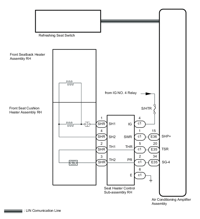
When the refreshing seat switch is operated, the air conditioning amplifier assembly receives the signal. The air conditioning amplifier assembly receives the signal and operates the front seat heater.
WIRING DIAGRAM
CAUTION / NOTICE / HINT
Note
-
Inspect the fuses and relays for circuits related to this system before performing the following inspection procedure.
-
First perform the communication function inspections in How to Proceed with Troubleshooting to confirm that there are no LIN communication malfunctions before troubleshooting this symptom.
PROCEDURE
-
CHECK FOR DTC
-
Clear the DTCs Click here.
-
Check for DTCs Click here.
Result Result Proceed to DTC B14C0 is not output A DTC B14C0 is output B
B 
GO TO DIAGNOSTIC TROUBLE CODE CHART Click here
A 
-
-
CHECK HARNESS AND CONNECTOR (BATTERY - SEAT HEATER CONTROL SUB-ASSEMBLY RH - BODY GROUND)
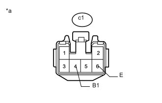
Text in Illustration *a Front view of wire harness connector
(to Seat Heater Control Sub-assembly RH)
-
Disconnect the seat heater control sub-assembly RH connector.
-
Measure the voltage and resistance according to the value(s) in the table below.
Standard Voltage Tester Connection Condition Specified Condition c1-4 (B1) - Body ground Engine switch on (IG) 11 to 14 V c1-4 (B1) - Body ground Engine switch off (IG) Below 1 V Standard Resistance Tester Connection Condition Specified Condition c1-6 (E) - Body ground Always Below 1 Ω
NG
REPAIR OR REPLACE HARNESS OR CONNECTOR
OK
-
-
INSPECT SEAT HEATER CONTROL SUB-ASSEMBLY RH
-
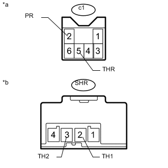
Text in Illustration *a Seat Heater Control Sub-assembly RH
(to Air Conditioning Amplifier Assembly)
*b Seat Heater Control Sub-assembly RH
(to Front Seat Cushion Heater Assembly RH)
Remove the seat heater control sub-assembly RH Click here.
-
Measure the resistance according to the value(s) in the table below.
Standard Resistance Tester Connection Condition Specified Condition c1-5 (THR) - SHL- 2 (TH1) Always Below 1 Ω c1-5 (THR) or SHL-2 (TH1) - Body ground Always 10k Ω or higher c1-2 (PR) - SHL-3 (TH2) Always Below 1 Ω c1-2 (PR) or SHL- 3 (TH2) - Body ground Always 10k Ω or higher
NG
REPLACE SEAT HEATER CONTROL SUB-ASSEMBLY RH Click here
OK
-
-
INSPECT FRONT SEAT CUSHION HEATER ASSEMBLY RH
-
Remove the front seat cushion heater assembly RH Click here.
-
Inspect the front seat cushion heater assembly RH Click here.
NG
REPLACE FRONT SEAT CUSHION HEATER ASSEMBLY RH Click here
OK
-
-
INSPECT FRONT SEATBACK HEATER ASSEMBLY RH
-
Remove the front seatback heater assembly RH Click here.
-
Inspect the front seatback heater assembly RH Click here.
NG
REPLACE FRONT SEATBACK HEATER ASSEMBLY RH Click here
OK
-
-
CHECK HARNESS AND CONNECTOR (SEAT HEATER CONTROL SUB-ASSEMBLY RH - AIR CONDITIONING AMPLIFIER ASSEMBLY)
-
Disconnect the E35 and E36 air conditioning amplifier assembly connectors.
-
Disconnect the c1 seat heater control sub-assembly RH connector
-
Measure the resistance according to the value(s) in the table below.
Standard Resistance Tester Connection Condition Specified Condition E36-15 (SHP+) - c1-1(SWR) Always Below 1 Ω E36-15 (SHP+) or c1-1 (SWR) - Body ground Always 10 kΩ or higher E35-20 (TSR) - c1-5 (THR) Always Below 1 Ω E35-20 (TSR) or c1-5 (THR) - Body ground Always 10 kΩ or higher E35-34 (SG-4) - c1-2 (PR) Always Below 1 Ω E35-34 (SG-4) - c1-2 (PR) - Body ground Always 10 kΩ or higher
NG
REPAIR OR REPLACE HARNESS OR CONNECTOR
OK
-
-
CHECK SEAT HEATER CONTROL SUB-ASSEMBLY RH
-
Replace the seat heater control sub-assembly RH Click here.
-
Check that the front seat heater system is operated normally.
OK The front seat heater operates normally.
OK
END (SEAT HEATER CONTROL SUB-ASSEMBLY LH)
NG
-
-
CHECK AIR CONDITIONING AMPLIFIER ASSEMBLY
-
Check that the front seat heater Click here.
OK
END (AIR CONDITIONING AMPLIFIER ASSEMBLY WAS DEFECTIVE)
NG
REPLACE REFRESHING SEAT SWITCH Click here
-