PRE-CRASH SAFETY SYSTEM Power Source Circuit
DESCRIPTION
This circuit supplies power to the seat belt control ECU when the ignition switch is ON.
WIRING DIAGRAM
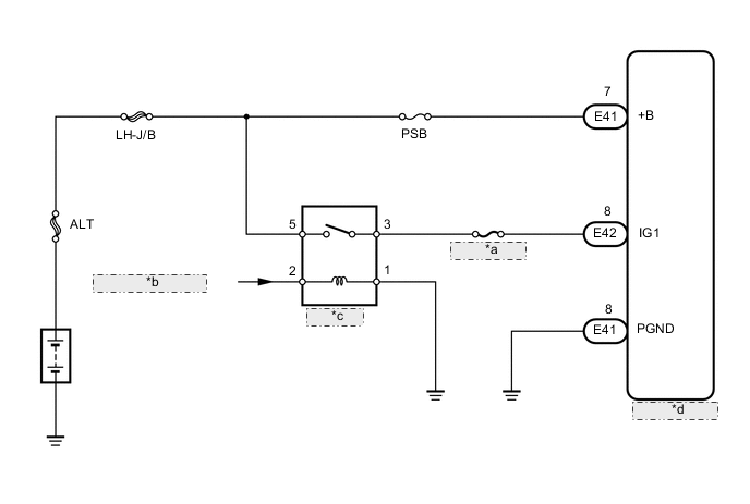
| *a | ECU-IG No. 1 |
| *b | from Main Body ECU |
| *c | IG1 NO. 1 |
| *d | Seat Belt Control ECU |
CAUTION / NOTICE / HINT
Tech Tips
Start the engine before inspection. Check the IG1 NO. 1 relay or battery if the starting system does not start.
PROCEDURE
-
INSPECT FUSE (ECU-IG No. 1, PSB)
-
Remove the ECU-IG No. 1 and PSB fuses from the main body ECU.
-
Measure the resistance according to the value(s) in the table below.
Standard Resistance Tester Connection Condition Specified Condition ECU-IG No. 1 fuse Always Below 1 Ω PSB fuse
NG 
REPLACE FUSE
OK 
-
-
CHECK HARNESS AND CONNECTOR (SEAT BELT CONTROL ECU - BATTERY AND BODY GROUND)
-
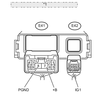
*1 Rear view of wire harness connector: (to Seat Belt Control ECU) Disconnect the E41 and E42 seat belt control ECU connectors.
-
Measure the voltage according to the value(s) in the table below.
Standard Voltage Tester Connection Switch Condition Specified Condition E42-8 (IG1) - Body ground Ignition switch ON 11 to 14 V Ignition switch off Below 1 V E41-7 (+B) - Body ground Always 11 to 14 V -
Measure the resistance according to the value(s) in the table below.
Standard Resistance Tester Connection Condition Specified Condition E41-8 (PGND) - Body ground Always Below 1 Ω Result Result Proceed to OK
(for LHD)
A OK
(for RHD)
B NG C
A
REPLACE SEAT BELT CONTROL ECU Click here
B
REPLACE SEAT BELT CONTROL ECU Click here
C
REPAIR OR REPLACE HARNESS OR CONNECTOR
-